U.S. Department of Transportation
Federal Highway Administration
1200 New Jersey Avenue, SE
Washington, DC 20590
202-366-4000
In Germany, the team met with representatives of the Federal Highway Research Institute, State of Bavaria Department of Highways and Bridges, German Association of Prefabricated Elements and Systems, Adam Hornig (contractor), and Elementbau Osthessen (prefabricator).
The road construction administrations in Germany are subject to the European Community's public procurement directives. Consequently, all road construction contracts must meet the available requirements of the European Union's (EU) technical specifications. These specifications are European standards, authorizations, and general technical specifications that have been incorporated into national standards. Where no European technical specifications exist, an EU member country can deviate from the standards. Certain products used for the construction of roads and bridges are governed by the European Construction Products Directive, which has been integrated into the Construction Products Act in Germany.
In 2003, 36,971 of the approximately 120,000 bridges in Germany were within the jurisdiction of the federal government. The federal bridges comprised 27.2 million m 2 (293 million ft 2) of bridge deck, of which 18.8 million m 2 (202 million ft 2) used prestressed concrete superstructures. The remaining bridges include 5.2 million m 2 (56.0 million ft 2) of reinforced concrete superstructures, 1.9 million m 2 (20.5 million ft 2) of steel superstructures, and 1.2 million m 2 (12.9 million ft 2) of composite structures. The annual maintenance cost for federal bridges is EUR350 million (US$420 million).
Germany has recognized the importance of accelerating construction on the autobahns that are particularly problematic or have heavy traffic volume. Therefore, when bidding on projects, contractors are invited to offer construction times shorter than those specified by the client. This "acceleration" is considered when awarding the contract.
The Federal Highway Research Institute (BASt) is a technical and scientific institute responsible to the Federal Ministry of Transport. Its overall objective is to improve the safety, economy, and operational efficiency of roads and to make them more environmentally friendly. Its staff of about 400 is involved in research, testing, certification, accreditations, and technical advice. Current research at BASt on concrete bridges includes the use of exchangeable pre- and post-tensioned cables, high-strength concrete to reduce self weight, and self-consolidating concrete.
The Department of Highways and Bridges in the Bavarian Road Administration is responsible for maintaining, operating, and improving a network of major roads in Bavaria—Germany's largest state. These include 2,300 km (1,400 mi) of federal motorways, 6,800 km (4,200 mi) of federal highways, 14,000 km (8,700 mi) of Bavaria's own highways, and 18,700 km (11,600 mi) of roads for which maintenance has been transferred to the Bavarian Road Administration, for a total length of about 42,000 km (26,000 mi).
Bavaria has closely tracked vacation traffic patterns and has established policies against lane closures during peak holiday periods. In particular, construction work is not allowed on the autobahn from July 18 to September 14, a peak travel period. Regulations also have been established to ensure that traffic keeps moving. The maximum length of any lane restriction is 12 km (7.5 mi) to allow a recovery distance. Minimum lane widths are 3.25 m (10.7 ft) for truck traffic and 2.75 m (9.0 ft) for cars. This regulation must be followed unless an exemption is obtained from the federal government.
Four levels of work operation have been established as follows:
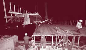
Nighttime operation is used only in special situations because of increased costs and concerns about quality. Working in daylight hours only is generally the most economical.
The state is willing to pay a premium to accelerate construction because the loss of production time caused by road construction is estimated to cost EUR1 billion (US$1.2 billion) per year. The maximum bonus for early completion or penalty for late completion of a project is 20 percent.
Bavaria follows the directive of the 1993 general circular described below in selecting types of construction. This means only 27 percent of the bridges use precast, prestressed concrete because they have to meet the same standards as CIP bridges. Consequently, it is easier to build a CIP bridge unless other criteria apply.
In 1993, the secretary of transportation issued a General Circular to the Principal Road Construction Authorities in Germany on the use of prefabricated, prestressed concrete beams for bridges on federal highways. The circular requested that prefabricated, prestressed concrete components be used only under the following conditions:
Finally, all prefabricated, prestressed components must adhere to the same principles for design, accessibility, inspectability, replaceability, and durability as cast-in-place concrete bridges.
The 1993 circular, together with previous experience and practices have led to the following principles for design and construction of concrete bridges in Germany :
As a result of these practices, the majority of bridge structures are built using cast-in-place concrete. Only 23 percent of modern bridges contain prefabricated elements with 15 percent of the bridges using prefabricated main beams. Different construction methods used in Germany are described in the following sections.
With concrete box girder bridges, external post-tensioning inside the box is preferred because maintenance and inspection are easier, tendons can be removed, grouting has been a problem with internal tendons, tendons can be added, and the cost is less.
In Germany, the technique of incremental launching has been well developed. It is used for constructing multispan bridges across valleys and where it is desirable to minimize interference with traffic. Typical span lengths are 20 to 40 m (65 to 130 ft), although span lengths up to 140 m (459 ft) have been used with steel girders. The launching of a steel box girder on a horizontal curve has been successfully completed.
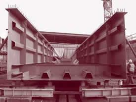
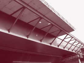
One example of an incrementally launched bridge is the Wupper Valley Bridge on Autobahn 1. This project involved expanding the existing expressway from four to six lanes, plus adding an emergency shoulder in each direction. The only solution was to build a second bridge parallel to the existing one. The new bridge is a seven-span structure with span lengths ranging from 44 to 72.8 m (144 to 239 ft) for a total length of 4,18.3 m (1,372 ft). The cross section of the bridge consists of a rectangular steel U-shaped box beam (shown in figure 21a) with deck cantilevers beyond the webs supported by inclined struts (shown in figure 21b). Partial-depth, precast concrete deck slabs were used to eliminate the need for falsework. The slabs were placed on soft polymer strips to seal the joints. Shear studs from the steel beams projected into openings in the precast slabs. These openings were filled with high-strength concrete before placing a CIP concrete deck.
 |
 |
 |
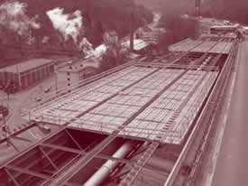 |
Figure 21. Incremental launching with precast concrete decks. (Photos courtesy of Strassen NRW.)
The structure was incrementally launched using hydraulic jacks that pushed on the end of the steel box beam. The piers were equipped with sliding bearings to facilitate the launching. The nose at the front of the structure was equipped with a hydraulically controlled lifting device that was used to raise the front of the structure as it reached each pier. Before launching, the precast concrete slabs in the midspan region were placed. The slabs over the supports were then placed from the other slabs. If the steel construction had been moved without the concrete slabs, the slabs would have had to be placed on the bridge from the side—resulting in additional impact on traffic. If all concrete slabs had been placed before launching the structure, the existing hydraulic equipment would not have had sufficient capacity. This structure was reported to be the first to use precast deck slabs of this size.
Historically, bridges with prefabricated elements were limited to pedestrian bridges. More recently, the industry has developed practices to address the design and construction requirements. Longitudinal continuity is provided by using CIP concrete decks and making the girders integral with the pier cap. Transverse continuity and evenness of the deck are also provided by the CIP deck. To provide the integral connection with the pier cap, the beams are temporarily supported on shoring, as shown in figure 22. The end of the beam is then encased in the pier cap and made integral with it. Longitudinal post-tensioning tendons over the pier cap may also be provided to increase the continuity. These tendons may also extend into the positive moment region. It has been found that the optimum economic solution is to provide about 50 percent of the prestressing in the precast, prestressed concrete beams and 50 percent as post-tensioning after erection.
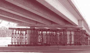
Figure 22. Temporary shoring for precast beams.
This method of construction also means that the bent cap has little protrusion below the bottom of the beams—an aesthetic condition that Germany prefers to increase the apparent slenderness of the bridge. It was observed in Europe that many bridges in residential neighborhoods have sound barriers. From the exterior elevation, these bridges look much deeper than equivalent span bridges without sound barriers.
Prefabricated concrete elements are used only in situations where a short construction time is needed, restrictions to traffic have to be minimized, or there is not enough space for formwork and falsework. Bridge construction cost data indicate that bridges using precast concrete are about 25 percent more expensive than cast-in-place concrete bridges.
The precast concrete industry is considering the use of high-strength concrete up to 100 MPa (14,500 psi) in beams, high-strength concrete in bridge decks in combination with steel beams, high-strength lightweight concrete, self-compacting concrete, and internal fabric grouted tendons that can be replaced.
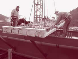
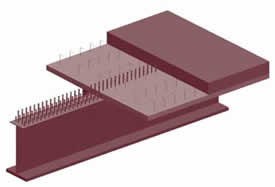
This system involves the casting of a partial-depth concrete deck on steel beams or concrete beams before erection of the beam. The system for a steel beam is illustrated schematically in figure 23a. With a steel I-beam, the prefabricated concrete deck is connected to the steel beams through studs welded to the beam. After the beams are erected, the edges of each deck unit almost touch each other so there is no need for additional formwork for the cast-in-place concrete. The system under construction is shown in figure 23b. In accordance with German practice, the ends of the steel girders are made integral with the bent cap either through studs connected to an end plate on the girder or by extending the web into the abutment with studs attached to the web, as shown in figure 23c. With an inverted steel tee-beam, the details shown in figure 23d may be used to connect the beam to the prefabricated concrete deck.
 |
 |
 |
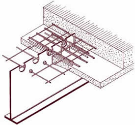 |
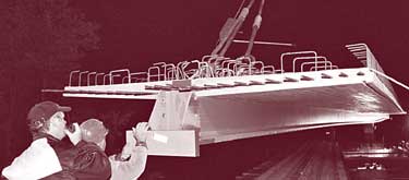
Figure 23. Partial-depth concrete deck prefabricated on steel beams. (Drawings and photographs courtesy of Bavarian Department of Highways and Bridges.)
An alternative arrangement of the same system is shown in figure 23e. In this arrangement, the steel girder consists of two inverted steel tee-beams placed side by side and connected along their bottom flanges. The space between the two webs is filled with concrete at the same time the prefabricated deck is cast. Appropriate reinforcement is provided to make the member composite.
The same partial-depth concrete deck system is also used on prestressed concrete beams, as shown in the completed bridge in figure 22. Before erection, the beam resembles a deck bulb-tee beam, except the deck is not full depth. A typical cross section is shown in figure 24.
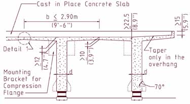
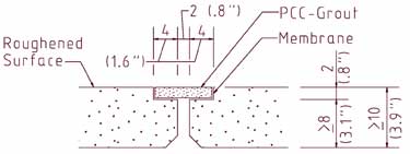
Figure 24. Partial-depth concrete deck on concrete beams. (Based on drawings supplied by Bavarian Department of Highways and Bridges.)
A typical bridge deck multiple-level corrosion protection system, shown in figure 25, consists of the following layers of material from top to bottom:
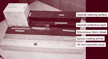
Figure 25. Bridge deck multiple-level corrosion protection system.
The system has been used since the mid 1980s. Previously, a system of asphalt overlay on a sheet of mastic on glass fleece had been used, but the system did not provide the necessary protection against the ingress of water containing deicing salts. The use of waterproofing systems in other European countries is discussed in NCHRP Report 381— Report on the 1995 Scanning Review of European Bridge Structures.
Gussasphalt is one material used on bridge decks. It consists of a dense mix of filler, sand, grit or gravel, and bitumen. Various categories of hardness are available, depending on the anticipated stresses and indentation depths. Requirements for Gussasphalt when used as a protective or intermediate layer on bridges are given in ZTV-BEL-B (Additional Technical Contract Conditions and Guidelines for Production of Concrete Bridge Decks) and ZTV‑BEL‑ST (Additional Technical Contract Conditions and Guidelines for Production of Steel Bridge Decks). Both documents are published by the Federal Department of Transportation, Construction, and Housing (BMVBW).
In Germany, a detailed description of the noise protection "galerie" on Hansa Street, Wuppertal, was provided. The gallery consisted of a noise protection cover over half of an existing expressway with an existing retaining wall on one side. It involved construction of an edge beam attached to the retaining wall, precast L-beams supported on columns on the other side of the expressway, precast tee-beams spanning the highway, a CIP-reinforced concrete deck, and sound-absorbent precast concrete wall panels. A photograph of the construction is shown in figure 26.
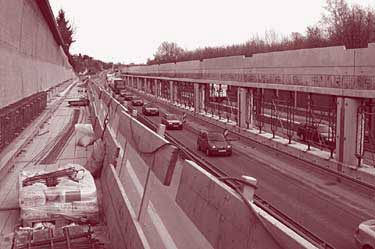
Figure 26. Construction of a noise protection gallery. (Photo courtesy of Strassen NRW.)
The team also visited several bridge sites to view completed bridges and one bridge under construction. These included the BW116, BW117, BW108, and BW101 bridges on the A9 near Munich; BW 19 and BW20 on the A8 West near Munich; and two bridges on the A3 Anschlussstelle Frankfurt Sud near Frankfurt. A summary of the six bridges visited in Bavaria is given in table 3. One common feature of these bridges is that separate formwork was not required to support the concrete deck. As a result, a working surface was available as soon as the beams were erected. This provided a platform for workers above the active highway and protected the traveling public from falling objects. Speed of construction was also increased because placement of deck reinforcement could begin immediately.
| Bridge No. | Spans, m (ft) | Bridge Type | Year Built |
|---|---|---|---|
| BW116 on A9 | One at 11.5(37.7) | Adjacent inverted precast tee-beams, 600 mm (23.6-in) deep, with the entire void filled with CIP concrete. | 1976 |
| BW117 on A9 | One at 6 (19.7) | Adjacent precast deck bulb-tee type beams, 900 mm (35.4-in) deep, with a 3.5-m (11.5-ft) wide top flange and 200-mm (7.9-in) thick CIP slab. | 1976 |
| BW108 on A9 | Two at 22.9(75) | Adjacent precast deck tee-beams, with a 2.3-m (7.6-ft) wide top flange and 230-mm (9.1-in) thick CIP slab. | 1977 |
| BW101 on A9 | Two at 26.0 (85) | Adjacent precast deck-tee beams, with a 2.3-m (7.6-ft) wide top flange and 230-mm (9.1-in) thick CIP slab. | 1977 |
| BW19 on A8 West | Two at 24.7 (81) | Adjacent precast deck-tee beams, 1.05 m (3.44-ft) depp with a 2.71-m (8.88-ft) wide top flange and 250-mm (9.8-in) thick CIP slab. | 1976 |
| BW20 on A8 West | One at 46.5 (153) | Variable depth steel I-beam with a prefabricated concrete top flange, 100 mm (3.9-in) thick, and 250-mm (9.8-in) thick CIP slab. | 2002 |
Bridge BW19 was originally designed as a CIP structure, but the contractor proposed a precast alternate to speed construction and reduce traffic interruption on the autobahn. Longitudinal continuity was established with reinforcement projecting from the end of the prestressed concrete beams into the diaphragm.
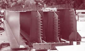
Bridge BW20, shown in figure 27, is a 46.5-m (153-ft) long single-span structure across six lanes of autobahn, two shoulders, and a central reservation. The ends of the beams, shown in figure 27b, are anchored into the abutment to provide fixed end supports. The bridge used the concept of prefabricating a 2.45-m (8-ft) wide, 100-mm (3.9-in) thick partial-depth concrete deck on the girders before erection. The top flange served as the compression flange as well as stay-in-place slab formwork for the CIP deck.
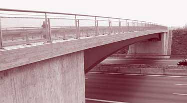
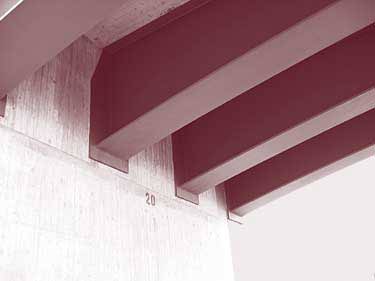
Figure 27. Variable-depth steel beam bridge.
The scanning team visited two bridges near Frankfurt. The first bridge (No. 5917-895) carries Federal Route B44 over BAB A3 that connects Munich to Cologne. The successful contractor had bid the original design, which used steel girders and a concrete deck. The same contractor also provided a lower bid for a precast, prestressed concrete design-build alternate. The alternate was selected because it minimized traffic disruption and could be built faster than the original steel girder bridge design.
The bridge, shown in figure 22, is a two-span continuous structure with a width of 23.5 m (77.1 ft) and span lengths of 25.45 and 28.20 m (83.5 and 92.5 ft) at a 37-degree skew. The five precast, prestressed concrete tee-beams for each roadway are spaced at 2.28 m (7.48 ft) and are made integral with the CIP pier cap and abutments. The CIP deck thickness is 230 mm (9.1 in).
The cross-section of each girder resembles a tee-shaped section with a total depth of 1.40 m (55 in). The top flange has a width of 2.26 m (7.41 ft) and a thickness of 120 mm (4.72 in). The web has a width of 660 mm (25.4 in) at its lower edge and tapers to a width of 460 mm (18.1 in) at the intersection with the top flange. Two-stage prestressing for the girders was used because of limitations of the prestressing bed. The girders were initially pretensioned and then post-tensioned before shipping. Specified compressive strengths were 45 and 55 MPa (6,500 and 8,000 psi) at release and 28 days, respectively. Each girder weighed about 85 t (94 tons).
For erection, the girders were placed on the temporary erection towers shown in figure 22. Each girder required only 10 minutes to place. After the girders were made integral with the pier caps and the abutment, the temporary towers were removed. The bridge is being built in two phases. At the time of the site visit, the west side of the structure was complete, the old bridge was demolished, and construction was proceeding on the east side.
Corrosion protection for the deck consisted of 60 mm (2.4 in) of concrete cover to the reinforcement, a sprayed-on polymer seal, a waterproof membrane, and two layers of asphalt with thicknesses of 35 and 40 mm (1.4 and 1.6 in). For aesthetics, the concrete surfaces were cast against wooden boards and the abutment wing walls included a masonry brick inlay.
The second bridge visited was BAB A3 bridge over a connector road to A66. The bridge is a three-span, precast, prestressed concrete girder bridge with a cast-in-place concrete deck. The intermediate piers consist of four columns with a bent cap supported on bearings, as shown in figure 28. Overall, the bridge system was similar to the previous bridge, except for the method of construction. Before the precast girders were erected, the bent caps were cast with a ledge to support the precast girders. The cross section of the intermediate bent cap, therefore, was very similar to an inverted tee-beam and the bent cap at the abutment resembled a ledger beam. The precast girders were then erected and additional reinforcement was placed in the bent caps to make the girders integral. The remaining portions of the bent caps were cast at the same time as the deck.
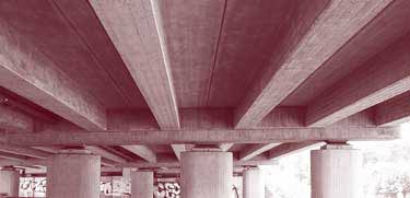
Figure 28. Precast, prestressed concrete bridge.
The contractor stated that the use of precast, prestressed concrete tee-beams reduces construction time compared to the use of steel girders with a prefabricated concrete deck. In both cases, the use of the prefabricated decks on the girders before erection reduces construction time compared to the use of conventional formwork.
| << Previous | Contents | >> Next |

