U.S. Department of Transportation
Federal Highway Administration
1200 New Jersey Avenue, SE
Washington, DC 20590
202-366-4000
In France, the team met with representatives of the National Engineering Division of the French National Railway Authority (SNCF), Technical Department for Public Works and Transportation (SETRA), Central Laboratory for Public Works (LCPC), Technical Center for the Concrete Industry (CERIB), Technical Studies Center for Public Works (CETE), CPCBTP (producer), and Lafarge Cement. The team visited three bridge sites.
The main criterion for bridge repair, replacement, or new construction on the French railways is to minimize the disturbance to rail traffic. Consequently, a wide range of construction techniques is used, depending on the type of structure, site constraints, and available access.
Continuous structures are preferred because of improved dynamic performance, reduced deflection and rotation, absence of joints, use of a single line of bearings, and reduced maintenance. These factors are very important for the high-speed rail system. The structural system is selected to meet the design criteria. No tensile stresses are allowed in the concrete, and the reinforcing steel stress is limited to either 200 or 240 MPa (29,000 or 34,800 psi). Limits are also placed on the vertical acceleration of the deck.
Contractors pay a penalty if completion of construction is delayed. The penalty is based on the extent of actual costs to the railroad for diverting trains and modifying operations.
The traditional method of installing a railway bridge that has been in use for 50 years is to build the foundations, piers, and abutments while the existing track is in service. The new bridge is then built alongside the existing railway line. With a short interruption to railway traffic, the bridge is then moved laterally into its final position.
For span lengths up to about 12 m (39 ft), quick bridge replacements can be made using conventional heavy-duty cranes. If two rail tracks are available, the work is performed in two phases, while the traffic in both directions uses one track with speed restrictions. Where access is limited, the new bridge may be delivered to the site along the railroad track using a special train. The desire to further reduce interruptions to traffic has led SNCF to additional innovative methods as described in the following sections.
The Pont de St. Denis was a 19 th century steel truss bridge spanning a canal, and needed to be replaced because of fatigue problems and the use of higher axle loads. One track was closed to trains while the new bridge was delivered to the site along the track using SPMT, as depicted in figure 29a. Extension brackets were mounted on both ends of the new bridge. Once in position above the old bridge, the extension brackets were used to support the new bridge on the abutments, as shown in figure 29b. The old bridge was supported by suspension rods from the new bridge so the old bridge could be cut into sections and lowered onto barges in the canal to be taken away (figure 29c). The new bridge was supported by bearings and jacks on the abutments while the extension brackets were removed (figure 29d). Finally, the new bridge was lowered into its final position (figure 29e). The bridge was replaced in 3 days.


![]()
Figure 29. Replacement sequence of the Pont de St. Denis. (Based on drawings by SNCF.)
The Viaduc de Lamothe was a 19 th century steel lattice bridge near Toulouse in southwest France and required replacement. The new bridge was built inside the lattice bridge, and the old bridge was then removed. Replacement was completed in 4 to 5 weeks. The old and new bridges are shown in figure 30.
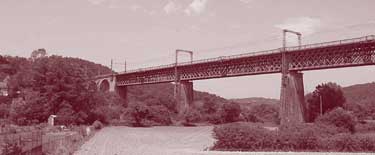
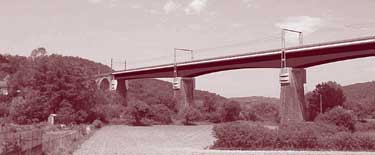
Figure 30. Viaduc de Lamothe. (Photos courtesy of SNCF.)
At St. Pierre du Vauvray, an original method of laterally launching was used to eliminate a grade crossing and provide a road underpass with only a 22-hour interruption to train traffic. The contractor excavated a large pit next to the railroad tracks and built a reinforced concrete box culvert in the pit. Then, 1,250 m 3 (1635 yd 3) of soil was excavated from beneath the railroad tracks. The excavation was sealed to form a cofferdam, and the excavation was flooded. The 855-t (950-ton) culvert was floated into position, as shown in figure 31. This method is mainly useful where there is an ample water supply.
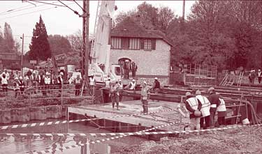
Figure 31. Floating a culvert into position. (Photo courtesy of SNCF.)
An unusual technique was used on the Viaduc do Ventabren, south of Avignon in Provence. A variable-depth, CIP balanced cantilever bridge was built on a pier alongside the existing highway. The 2,400-t (2,650-ton), 80-m (262-ft) long superstructure was then rotated about 45 degrees to span the highway. The superstructure was supported on eight Teflon® bearing pads to reduce the friction to 5 percent. A guide pin in the center of the pier acted as a pivot. Three synchronized hydraulic jacks were used to rotate the superstructure, while eight vertical jacks were used to lift the bridge periodically to allow restroking of the jacks and repositioning of the bearings. After the bridge was in its final position, the sliding bearings were replaced with permanent ones. A time-lapse photograph of the rotation is shown in figure 32.
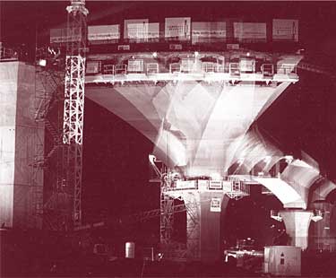
Figure 32. Time-lapse photograph of rotating a balanced cantilever bridge. (Photo courtesy of SNCF.)
The French railways have used SPMT to move bridges into place. The Viaduc de Mornas is a steel bowstring bridge for high-speed rail and crosses a river. The bridge was built on the bank and, using SPMT, rolled across the river with one end on a barge before arriving on the other bank. Tolerances of final placement using the SPMT were 0 mm (0 in) in the longitudinal and transverse directions and 50 mm (1.97 in) vertically. For skidding, a tolerance of 50 mm (1.97 in) is allowed in all directions.
Site visits were made to two railroad bridges and one highway bridge under construction. During travel for the site visits, the team observed that the French also use transparent sound barriers on their bridges.
The first railroad bridge, identified as PRA 1309, was a four-span structure across a new highway at Nonant le Pin. The bridge was constructed on the concrete slab shown in the foreground of figure 33. It was moved 44.5 m (146 ft) into position using SPMT. To accomplish the move, pairs of temporary concrete beams were cast between the three piers. SPMT then lifted the beams and moved the bridge. After the bridge was positioned, the beams were dismantled by being cut into sections to reduce their hauling size and weight. In figure 33, the center portions of the beams from each span are lying on the ground, while stub beams remain protruding from the piers. These subsequently will be removed. To accomplish the bridge placement, the track was closed for 48 hours. Total time for moving the 2,000-t (2,200-ton) bridge was 8 hours. The average speed of travel was 200 mm/min (7.9 in/min).
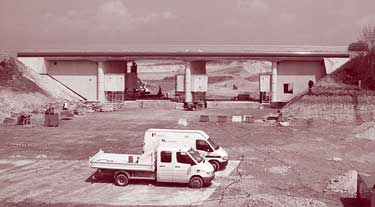
Figure 33. Railway bridge moved using SPMT.
The second railway bridge, identified as PRA 3265, was a four-span, 3,300-t (3,600-ton) structure across the new A28 highway. At the time of the site visit, construction of the bridge adjacent to the railroad track was almost complete, as shown in figure 34. The bridge will be slid from its construction location to its final position. To accomplish the move, the bridge has been built on two foundation slabs—one on top of the other. The top slab is connected to the piers. The base slab provides a foundation for building the bridge and a sliding surface for the upper slab. The bridge will be moved into its final position now occupied by the embankment in the background of figure 34 by sliding the top slab over the bottom one. To reduce friction between the two slabs, a waxed and greased plastic membrane is placed between them. Bentonite is pumped through tubes in the top slab to the interface to act as a lubricant and to fill voids in the soil as the top slab slides off the base slab onto the ground. The same tubes are later used for grouting underneath the top slab when it is in its final position. In its final location, the bearing pressure beneath the slab is less than the soil pressure before removal of the embankment. Consequently, a slab foundation could be used.
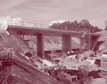
Figure 34. Railway bridge before sliding into place.
The base slab also provides directional guidance to the top slab, as shown in figure 35. The top slab sits in a slight recess in the base slab. Plastic sheets separate the vertical faces of the two slabs. The leading edge of the top slab is tapered on the underside and is reinforced with a steel angle.
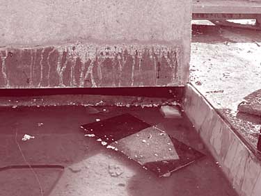
Figure 35. Leading edge of upper slab before sliding.
The railroad bridge will be pushed into place using four strand jacks pulling on tendons anchored at the leading edge of the base slab. Each tendon consists of 37 15.2-mm (0.6-in) diameter strands. The anticipated rate of movement is 8 m/h (26 ft/h) over a 6-hour period. Final placement tolerance is plus or minus 20 mm (0.8 in). The contractor chose the sliding method rather than SPMT because of greater familiarity with the sliding method.
The highway bridge under construction was a curved continuous 13-span, composite steel girder, concrete deck bridge across the Risle River Valley, as shown in figure 36. Span lengths are about 60 m (197 ft). The girders were assembled behind each abutment in 180-m (590-ft) lengths and launched longitudinally in increments of 120 m (394 ft). The girders were precambered for dead load deflection. The nose at the leading edge of each pair of beams is guided laterally by jacking at every other pier. Lateral adjusted roller bearings are used to accommodate the lateral movement as the bridge is launched.
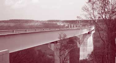
Figure 36. Risle River Viaduct under construction.
After the complete superstructure is launched, formwork for supporting the deck will be rolled forward. A deck-casting sequence to minimize cracking in the negative moment region will be used. The longitudinal launching method of construction is common in France for multispan structures across valleys and was reported to be economical.
The Ministry of Public Works' Directorate of Roads and Directorate of Road Safety and Traffic are responsible for 9,700 km (6,000 mi) of motorways and 27,000 km (17,000 mi) of national roads in France. Although national roads constitute only 4 percent of the total road network, they carry 40 percent of the traffic. The technical network of the Directorate of Roads and the Directorate of Road Safety and Traffic includes SETRA, LCPC, and CETE.
Service d'Étude Techniques des Routes et Autoroutes (SETRA) operates under the Ministry of Public Works and has a staff of about 400. Its mission is to generate and define French road doctrine, guarantee the quality of projects, develop partnerships, and cooperate with the international community.
The Laboratoire Central des Ponts et Chaussées (LCPC) is a state-owned institute under the authority of the Ministry of Public Works and the Ministry for Research.
Under its 2001 to 2004 contract, the five priorities of LCPC are as follows:
The eight Centres d'Etudes Techniques de l'Equipement (CETE) are part of the technical network headed by LCPC. LCPC has an annual budget of EUR43 million (US$52 million) and 600 permanent employees. It has partnerships with various other organizations in France, Europe, North America, and Asia.
The Centre d'Étude et de Researches l'Industrie du Béton (CERIB) is a nonprofit public sector organization with a mission to contribute to technical progress, improve productivity, and develop quality in the concrete industry. It is funded from a mandatory tax paid by all French concrete manufacturers and revenues from various services.
The main owners of road bridges in France are the national government, local authorities, and tollway authorities. Each retains the right to deploy its own bidding procedures. The bidding process may involve competitive bidding, design-build competition, or performance guarantees. Selection criteria for contracts include operating costs, technical validity, construction time, aesthetic and functional features, and price. The owner defines the weighting of each criterion before bidding. The following is a typical sequence of relative importance:
Contractors are allowed to submit alternate designs, but must conform to certain criteria such as span lengths, environmental impact, and construction time. For most projects, initial cost is the leading criterion, but life-cycle cost is considered for about 10 percent of the projects.
Prefabrication of bridges in France began after World War II with a progression from reinforced concrete beams to prestressed and post-tensioned concrete beams. Nevertheless, most bridges are still built using CIP concrete because each architect wants a different structure, each bridge has different dimensions, and sizes have not been standardized. Most contractors are well equipped to build post-tensioned bridges. In the past 50 years, 1,600 post-tensioned bridges have been built in France, including the Saint-Nazaire sur la Loire Bridge with 50 spans of 50 m (164 ft). Some bridges built in the period before 1965 to 1970 have experienced problems because of underestimated prestress losses, insufficient reinforcement, poor quality of grout injection in ducts, and lack of sealing of the decks where salt is used. Membranes were not used before 1970, but are now used on bridge decks together with asphalt wearing surfaces.
A typical pretensioned concrete bridge for a span length of 20 m (65 ft) consists of I-beams at 1-m (39-in) centers with a CIP concrete slab having a thickness of 180 to 200 mm (7 to 8 in). For spans of 10 to 15 m (33 to 49 ft) and possibly up to 20 m (66 ft), rectangular or trapezoidal section members are used. For spans of 15 to 25 m (49 to 82 ft), I-beams are used. For spans of 20 to 30 m (65 to 98 ft), I-beams with thickened ends to accommodate the higher shear forces are used. Other types of sections used to a lesser extent include double-tee and adjacent box beams. The latter have experienced problems with infiltration of water at the CIP longitudinal joint between boxes when membranes were not used.
The French prefer to minimize the number of bearings at supports and provide continuity by casting and connecting the ends of the precast beams into the cast-in-place bent caps or diaphragms. Positive moment connections are provided. This method is similar to that used in Germany and requires temporary supports for the beams before casting the bent cap or abutment diaphragm. The French also indicated that a single transverse line of bearings provides a more aesthetic appearance than having bearings under each beam at an intermediate support.
The following sections provide information on other systems described to the scanning team.
The Poutre Dalle System consists of shallow, precast, prestressed concrete inverted tee-beams, as shown in figure 37. The beams are placed next to each other, connected with a longitudinal joint, and covered with CIP concrete. Continuity along the longitudinal joint is established through the use of 180-degree hooks that protrude from the sides of the webs. The hooks overlap those from the adjacent beam, as shown in figure 38. The hooked bars are positioned precisely to avoid conflicts at the jobsite. Additional rectangular stirrups may be placed in the space between the webs of adjacent beams. Longitudinal reinforcement is placed inside the stirrups and hooked bars.
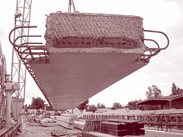
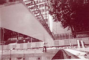
Figure 37. Poutre Dalle system. (Photos courtesy of CPC.)
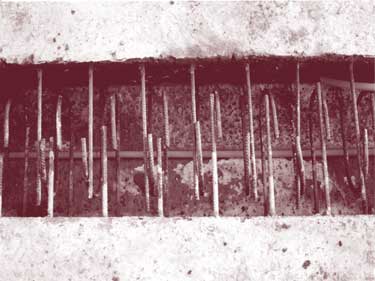
Figure 38. Overlapping bars in longitudinal joint. (Photo courtesy of CPC.)
The system is appropriate for span lengths of 6 to 25 m (20 to 82 ft), but can be extended to 32 m (105 ft). The overall depth including the CIP concrete for simple spans is 1/28 to 1/30 of the span length. The beam width is selected based on a 25-t (27.5-ton) shipping weight and varies from 400 to 2,000 mm (16 to 79 in). The ends of the beams can be made integral with the bent cap or abutment. A typical bridge can be erected in one day.
The system was reported to have the following advantages:
The system is certified by SNCF and SETRA and is proprietary in Europe.
The Dalle Preflex system is similar to the Poutre Dalle system, but uses steel I-beams with their bottom flanges precast in a 150-mm (5.9-in) thick prestressed concrete slab, as illustrated in figure 39. The units are placed next to each other. Hooked bars passing through the steel web overlap hooked bars from the adjacent members to provide lateral continuity. Additional reinforcement—including rectangular stirrups, transverse reinforcement through the hooked bars and stirrups, and longitudinal and transverse reinforcement in the top—are used to provide continuity. Cast-in-place concrete is used to complete the system. The system has similar advantages as the Poutre Dalle system and is proprietary in Europe.


Figure 39. Dalle Preflex system. (Based on drawings supplied by CPC.)
One form of construction used in France consists of two longitudinal steel beams supporting full- width, full-depth precast concrete deck panels. The concrete panels, which are usually 12 m (39 ft) long and 2.5 m (8.2 ft) wide, are match cast, epoxied together, and longitudinally post-tensioned. Screws located in the panels are used to adjust elevations. As an alternate to match casting, a transverse CIP joint is used between panels. Reinforcement extending from the edges of adjacent panels overlaps within the joint to provide continuity. Studs are welded to the steel beams through pockets in the panels. The panels sit on continuous elastomeric pads that also provide a seal for the grouting between the panels and the steel girder. The grout is injected through the stud pockets before the pockets are filled with concrete. Photographs of the system are shown in figure 40.
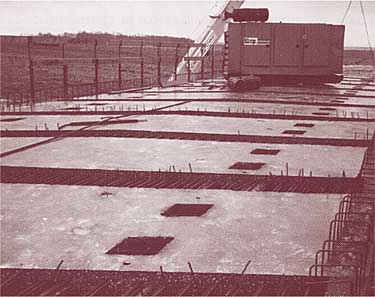
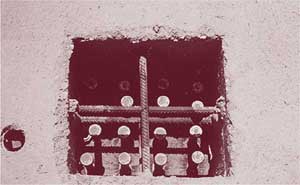
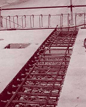

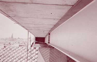
Figure 40. Full-depth, full-width precast deck panels. (Photos and drawing courtesy of LCPC.)
Another variation of full-depth precast deck panels is illustrated in figure 41. The center portion of the bridge consists of CIP concrete on the top flanges of a 6-m (19-ft) wide steel box girder. Precast panels on both sides of the box girder extend the deck width to 23 m (75 ft). The panels are prestressed in the transverse direction to prevent cracking. Cast-in-place joints above the transverse steel beams are used to provide longitudinal continuity and to connect the concrete panels to the steel beams.
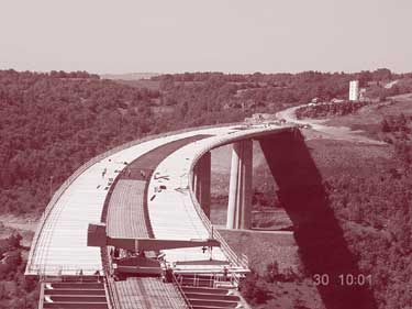
Figure 41. Full-depth precast deck panels. (Photo courtesy of LCPC.)
Ultra high-performance concrete (UHPC) is a combination of fine materials that produces a highly durable concrete with compressive strengths in excess of 150 MPa (22,000 psi) and as high as 250 MPa (36,000 psi). The first research was conducted by Bouygues on reactive powder concretes in 1990 to 1995. Several different formulations are available and have been used in practical applications. Worldwide bridge-related applications include the following:
The two road bridges at Bourg Les Valence consist of two simple spans of 22 m (72 ft). The superstructure consists of precast, prestressed concrete beams that resemble a double-tee beam, but the webs and bottom flanges are similar to an AASHTO girder cross section. A CIP longitudinal joint is provided between the flanges of the beams. The use of UHPC permitted a reduced deck thickness. The UHPC mix proportions and concrete properties are given in table 4.
Before construction of the bridges, a trial section of a beam was cast and then cut into pieces to produce specimens for full-size flexural tests. In concrete production, the water, high-range water reducer, and fibers were added to the other premixed ingredients. Average mixing time for 1 m 3 (1.3 yd 3) of material in a pan mixer was 15 minutes. In concrete placement, care was needed to limit the flow of the concrete to prevent segregation.
| Materials | kg/m2 | lb/yd2 |
|---|---|---|
| Cement | 1,114 | 1,878 |
| Silica fume | 169 | 285 |
| Aggregate 0 to 6 mm | 1,072 | 1,807 |
| Fibers | 234 | 394 |
| High-range water reducer | 40 | 67 |
| Water | 209 | 352 |
| Water-cement ratio | 0.19 | 0.19 |
| Properties | ||
| Compressive strength at 28 days | 175 MPa | 25,400 psi |
| Direct tensile strength at 28 days | 8 MPa | 1,160 psi |
| Post-cracking direct tensile strength at 28 days | 9.1 MPa | 1,320 psi |
| Modulus of elasticity | 64 GPa | 9,280 ksi |
| Density | 2,800 kg/m3 | 175 lb.ft3 |
The Shepherd's Creek Bridge in New South Wales, Australia, is a single 15.4-m (50.5-ft) span bridge, 21 m (69 ft) wide, that carries four lanes of traffic. The superstructure consists of 16 precast, prestressed, UHPC beams with a depth of 600 mm (23.6 in), spaced at 1,300 mm (51 in); 25-mm (1-in) thick precast UHPC stay-in-place formwork panels; and a 170-mm (6.7‑in) thick CIP concrete deck. The precast panels were heat cured at 60 to 90 degrees Centigrade (140 to 194 degrees Fahrenheit) for 2 to 3 days to eliminate shrinkage and significantly reduce creep.
Further details on the behavior and mechanical properties, structural design methods, and durability of HPC are available in a report entitled Ultra High-Performance Fibre-Reinforced Concretes—Interim Recommendations, published by SETRA and the French Association of Civil Engineers (AFGC).
The goal of the French program is to develop performance-based specifications for durability to be able to proportion concrete mixtures capable of protecting structures against a given degradation for a specified service life in given environmental conditions. The process involves identifying the relevant parameters related to the durability of concrete and reinforced concrete structures and developing performance criteria for the parameters. The parameters (called indicators by the French) are divided into universal indicators and indicators specific to a given degradation. Universal indicators are water porosity, chloride ion diffusion, gas permeability, water permeability, and calcium hydroxide content. Specific indicators related to alkali-silica reactivity, for example, are the amount of reactive silica released from aggregates with time and the total amount of alkalis. For each indicator, a standard test that can be easily performed in the laboratory is needed.
For the universal indicators, performance criteria for five levels of durability have been developed for each indicator. The performance criteria also have been related to service life ranging from less than 30 years to more than 120 years under different environmental conditions such as exposure to salt spray, immersion in seawater, or presence in a tidal zone.
The next step in the process is to monitor actual performance of bridges so that the "residual" durability life can be determined. Several field studies are underway to verify the approach. The prediction model was used in the design of the Vasco Da Gama cable-stayed bridge across the Tagus River at Lisbon, Portugal. It is expected that the methodology will be introduced into the Eurocode in the near future. Based on its research, LCPC has concluded that high-performance concretes provide a more durable concrete and better protection of the reinforcement against corrosion.
| << Previous | Contents | >> Next |