U.S. Department of Transportation
Federal Highway Administration
1200 New Jersey Avenue, SE
Washington, DC 20590
202-366-4000
In the Netherlands and Belgium, the team visited the head offices and facilities of two worldwide companies that specialize in lifting and moving heavy equipment and structures, including bridges. In the Netherlands, the team visited the Mammoet Corporation. In Belgium, the team visited the Sarens Group. In terms of lifting capacity, Mammoet ranks second in the world and Sarens ranks fifth.
Mammoet has annual revenues of about EUR300 million (US$360 million) and 1,700 employees at 42 locations in Europe, North and South America, Asia, Middle East, and Africa. In the United States, the company's offices are located near Atlanta, GA ; Baton Rouge, LA ; Houston, TX ; and Los Angeles, CA. Its equipment includes 650 cranes with capacities ranging from 30 to 4,400 t (33 to 4,850 tons), jacking and skidding equipment with a lifting capacity of up to 25,000 t (27,500 tons), tower systems with a capacity of up to 4,000 t (4,400 tons) and 2,000 axle lines of platform trailers, as well as other lifting and transporting equipment. Mammoet is involved in heavy lifting for the petrochemical, offshore, power, and civil engineering industries.
Sarens is a group of 30 companies with annual revenues of about EUR150 million (US$180 million) and 830 employees located in Belgium, the Netherlands, France, United Kingdom, Germany, Scandinavia, Southern Europe, Eastern Europe, Africa, Middle East, United States, South America, Asia, and Australia. Sarens' equipment includes 600 hydraulic cranes with capacities ranging from 20 to 1,000 t (22 to 1,100 tons), 110 crawler cranes of 50-to-2,000-t (55- to-2,200-ton) capacity, 500 axle lines of self-propelled modular transporters, and four 120-m (393‑ft) tall, 1,000-t (1,100-ton) capacity lifting towers, as well as other lifting and transporting equipment. About 50 percent of Sarens work is for the civil engineering industry, with the rest for the power, harbor works, and petroleum industries.
Both Mammoet and Sarens have their own engineering departments that develop detailed plans for moving heavy equipment. Staff training and safety of people and equipment are high priorities for both companies. Based on the information provided to the team, both companies have excellent qualifications and experience for moving both small and large bridges and bridge components. Their competitive edge is their ability to lift or move large structures.
In general, moving bridges or bridge components from their location of prefabrication to their final position involves one or more of the following basic methods:
The advantage of the driving method is that the bridge can be assembled at a location independent of its final position. It is moved from its assembly location to its final position using self-propelled modular transporters (SPMTs). In addition, height differences are adjusted easily using special support equipment, and differences in ground elevations are accommodated easily. The moving time can be relatively short. Two examples of moving large bridges are shown in figure 17. The bridge shown in figure 17a weighed about 3,300 t (3,600 tons), and was moved 120 m (390 ft) in about 2 hours to its final position across the A4/A5 expressway near Amsterdam 's Schipol Airport. SPMT with 134 axle lines were used. In figure 17b, twin steel arch bridges are being moved across a canal using a combination of SPMT and barges. Each bridge had a span length of 119 m (390 ft) and weighed about 800 t (880 tons).
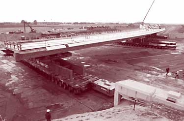
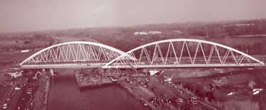
Figure 17. Moving large bridges with SPMT. (Photos courtesy of Mammoet Corp. and Sarens Group.)
The lifting method involves moving a bridge vertically using either hydraulic jacks or cranes. The method is largely place independent; height differences are easily accommodated but overhead wires and crane outriggers must be considered. The method is relatively quick, but crane capacity can be a limiting factor.
Pushing or pulling a bridge with hydraulic jacks from its point of fabrication to its final location requires a flat, well-built foundation, is limited to linear movement, and cannot compensate for any changes in height during the pushing or pulling operation. It can also be very time consuming compared to moving with SPMT.
Skidding along a specially prepared track requires a well-built foundation and is limited to a linear movement. Small differences in height can be tolerated by changes in the shape of the bridge. The process is also time consuming compared to moving with SPMT. As part of the Channel Tunnel Rail Link in the United Kingdom, a 9,500-t (10,500-ton) bridge including abutments and piers, shown in figure 18, was skidded into position in 72 hours. During transportation, only 16 mm (0.63 in) of deflection over the full length of the deck was permitted.
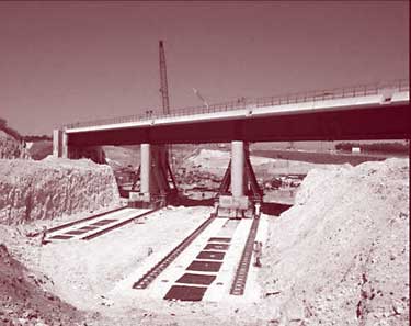
Figure 18. Skidding a bridge into position. (Photo courtesy of Mammoet Corp.)
Pivoting is a technique in which the bridge is built alongside the highway, railroad, or river, and then rotated around a vertical axis into its final position. It avoids constructing over the existing right-of-way.
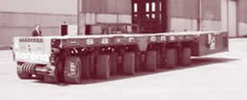
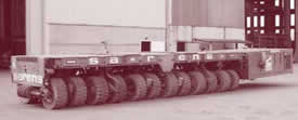
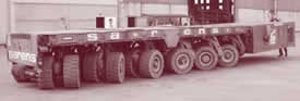
Of particular interest to the team for driving and lifting bridges were the computer-controlled, self-propelled modular transporters. A single SPMT, shown in figure 19, has either six or four axle lines. Each axle line consists of four wheels arranged in pairs and can support a maximum load of 30 t (33 tons) in addition to its own weight when ground conditions permit. Each pair of wheels can pivot 360 degrees around their support point. As a result, an SPMT has complete freedom of movement in all horizontal directions, as shown in figure 20.
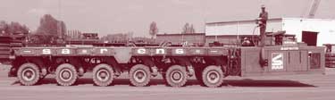
Figure 19. A single SPMT.
 |
 |
 |
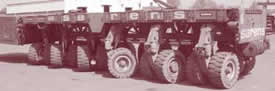 |
Figure 20. Directional capability of an SPMT.
Through its hydraulic suspension system, equal loads are maintained independently on each axle even on irregular surfaces. The bed of the SPMT can be raised by 600 mm (24 in) and tilted in both directions to maintain a horizontal bed on an inclined surface. Grades as steep as 8 percent have been used, but the maximum grade depends on site-specific friction. Vertical lifting equipment can be mounted on the SPMT platform if required. The SPMT is self propelled and can be coupled longitudinally and laterally to form multiple units all controlled by one driver. The driver walks with the units and carries a controller connected to the units by an umbilical cord. The controller has four basic commands: steering, lifting, driving, and braking. The approximate cost of one axle line is EUR125,000 (US$150,000). The SPMT can be transported to the bridge site on normal flatbed trailers or shipped in flat rack containers. The units have been used on several bridges in the United States, including the Lewis and Clark Bridge in Washington State ; the Wells Street Rapid Transit Viaduct in Chicago, IL ; and the 3rd Avenue Bridge in New York, NY.
In relocating bridges using SPMT, the following factors need to be considered:
| << Previous | Contents | >> Next |

