U.S. Department of Transportation
Federal Highway Administration
1200 New Jersey Avenue, SE
Washington, DC 20590
202-366-4000
In Japan, the scanning team visited three highway bridge projects and met with representatives of the Japan Highway Public Corporation, East Japan Railway Company, Mitsubishi Heavy Industries, Sumitomo Mitsui Construction Company, Mitsui Engineering & Shipbuilding Company, Japan Bridge Engineering Center, Japan Bridge and Structures Institute, Kajima Corporation, Kawada Industries, Oriental Construction Company, and Yokogawa Bridge Corporation. The involvement of these companies in one meeting reflects the spirit of cooperation that exists among owners, designers, and contractors. The scanning team observed that work is performed as a partnership to achieve a common goal.
The Japan Highway Public Corporation (JHC) is a special public corporation fully owned by the national government. It is responsible for constructing and operating expressways, ordinary toll roads, and toll parking facilities. It also is responsible for constructing rest areas, gas stations, and other facilities on expressways and expressway-related facilities, such as truck terminals and trailer yards. The corporation has about 9,000 employees and had an annual budget of ¥5,363 billion (US$50 billion) in 2001. The corporation is responsible for constructing the new Tomei Expressway between Tokyo and Nagoya and the new Meishin Expressway between Nagoya and Kobe. When completed, these two expressways will provide a 500-kilometer (km) (310-mile (mi) long link between three metropolitan areas as part of the national expressway network. The standard number of lanes is six throughout the expressway and the design speed is 140 kilometers per hour (87 miles per hour).
Employing rapid bridge construction techniques on road projects is a high priority in Japan for the following reasons:
Ten years ago, Japan had adequate labor to perform cast-in-place construction economically, but the reduction in skilled labor and rising labor costs have fostered growth of factory-produced, prefabricated components for bridge construction. This situation has encouraged Japanese engineers to search for ways to lower the size and weight of prefabricated components to satisfy hauling restrictions.
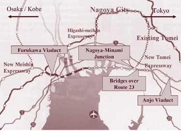
The three highway bridge projects the scanning team visited were the Anjo Viaduct, the Aritas Expressway (Route 23) and Nagoya-Minami Junction, and the Furukawa Viaduct, as shown on the map in figure 1. In addition, the team learned about other construction methods used in Japan. These projects and other construction methods are described in the following sections.
Figure 1. Map of bridge sites in Japan. (Map courtesy of JHC.)
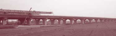
The Anjo Viaduct, shown in figure 2, is a horizontally curved bridge on the new Tomei Expressway and consists of 24 spans ranging in length from 31.5 to 40.5 m (103 to 133 ft) for a total length of 916 m (3,000 ft). The bridge consists of two parallel structures. The cross section of each superstructure consists of two precast, prestressed concrete, single-cell, constant-depth box girders with a total depth of 2.6 m (8.5 ft). The segments were match cast using the short-line method of casting. The weight of each segment was limited to about 30 t (33 tons) so that segments could be transported to the construction site on the public highway without a special permit. The deck of each segment is transversely pretensioned—a method not used in the United States. After each segment is removed from the casting bed, measurements of the segment are made with a three-dimensional measuring system that uses the principals of photogrammetry with high-precision cameras. The system provides automatic output of the measured shape, corrections for the next segment, measurement of time-dependent deformations, and erection simulation. The system was identified during the 1997 scanning study on Asian bridge structures. At that time, it was being used by the Yokogawa Bridge Corporation for steel bridge component measurements and erection simulation in lieu of shop assembly.
Figure 2. Anjo Viaduct.
The segments for the Anjo Viaduct were erected using the span-by-span method. An epoxy compound was applied to the joint surface of each segment, and the epoxy thickness was measured on each face before the segments were joined together. The span segments were connected to the pier segments using a cast-in-place (CIP) joint that contained stainless steel fibers and an expansive cement component. Each external longitudinal post-tensioning tendon consisted of 19 15.2-mm (0.6-in) diameter epoxy-coated strands located inside the box and passing through deviator blocks. For the pier segments, the transverse diaphragms were cast in place. Transverse post-tensioning was provided only at the pier diaphragms and in the deck above the deviator blocks.
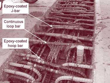
Pairs of side-by-side segments on each structure are connected together at the top flanges by a 600‑mm (24-in) wide longitudinal joint to form a continuous top surface for the roadway. Within the joint, hoop bars and J-bars projecting from the top flange of each pair of adjacent boxes overlap each other and are overlapped by a continuous loop bar, as shown in figure 3a. The bars projecting from the top slab, shown in blue in figure 3a, are epoxy-coated solely to prevent corrosion while the segments are in storage. Other bars pass through the loops to provide continuity. A cast-in-place concrete closure containing polyvinyl fibers is used to join adjacent segments. A photograph of the underside of the bridge showing the closure joint between segments is shown in figure 3b. A waterproof membrane and asphalt wearing surface will be applied to the deck surface.
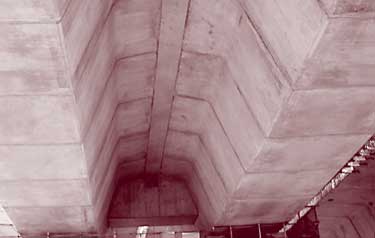
Figure 3. Longitudinal joint on the Anjo Viaduct.
One section of the New Tomei Expressway consists of an elevated structure that runs longitudinally above existing Route 23, which carries about 90,000 vehicles per day. Construction involved limiting the closure of Route 23 to 27 weekend nights for a total of 348 hours in 4 years. The new structure, therefore, was supported above the existing roadway, as shown in figure 4. Where sufficient working space existed alongside the highway, cast-in-place concrete piers were used. Where space was not available, prefabricated steel columns were used. Erection of the steel columns required lane closures.
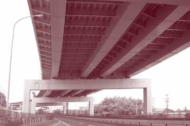
Figure 4. Elevated structure of Aritas Expressway. (Photo courtesy of JHC.)
For the erection of the steel beams across Route 23, steel stub beams were first attached to the columns on both sides of the highway, as shown in figure 5. Next, the highway was closed while prefabricated steel beams were connected between the ends of the stub beams to produce a span length of 33 m (108 ft).
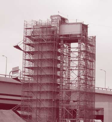
Figure 5. Concrete column with a steel stub beam.
Two methods were used to place the Aritas superstructure with minimum interruption to traffic. In the first method, each span was constructed on falsework alongside the existing roadway of Route 23. The superstructure units were slid horizontally sideways along the tops of the steel box beams to their final position above the existing highway. The second method involved prefabricating a curved steel girder and carrying it along the existing highway using special multiaxle transporters.
At the Nagoya-Minami Junction, three types of deck systems were observed—transversely prestressed, full-depth prefabricated concrete decks; a hybrid steel-concrete deck system; and orthotropic steel decks.
In recent years, the Japanese have started using precast, transversely pretensioned, full-depth concrete decks because of their improved durability, lower creep deformation, and faster construction, as shown schematically in figure 6a. In addition, wider girder spacings with fewer girders can be used compared to a CIP deck. The 2-m (6.6-ft) long, full-deck-width precast concrete panels are connected to steel girders using studs located in pockets in the panels, as shown in figure 6b. The studs are designed to provide a positive connection for lateral load only and not for composite action between the deck and the girders. The transverse joint between the panels consists of overlapping hoop bars that project from each edge of the panel. Individual bars are threaded within the loop bars to complete the connections, which are then encased in concrete. A schematic drawing of the deck joint reinforcement is shown in figure 6c. The decks are not post-tensioned longitudinally. All bridge decks in Japan receive a waterproof membrane and asphalt riding surface. The use of full-depth decks reduces construction time by eliminating the need to erect deck formwork and provide cast-in-place concrete. It also uses the advantages of a factory-produced product.
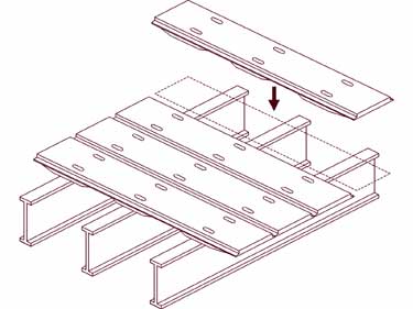
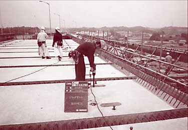

Figure 6. Full-depth prefabricated concrete deck. (Photo and drawings courtesy of JHC.)
Several Japanese companies have developed hybrid steel-concrete deck systems for bridges. One system is shown in figure 7. The steel component of the system consists of bottom and side stay-in-place formwork and transverse beams. The transverse beams span over the longitudinal beams and beyond the fascia beam for the slab overhang. The bottom flanges of the transverse beams support the steel formwork for the bottom surface of the slab. The formwork is sloped to provide a haunched section over the girders. The longitudinal deck reinforcement is supported by the top flange of the transverse beams. Steel studs welded to the beam flange connect the deck and the beams. When filled with concrete, the system acts as a composite deck system. The system allows rapid placement with a small-capacity crane of a lightweight deck stay-in-place formwork system complete with reinforcement, including the overhang.
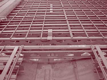
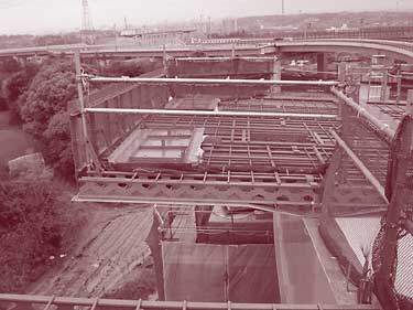
Figure 7. Hybrid steel-concrete deck system. (Photos courtesy of JHC.)
In recent years, the Japanese have developed an orthotropic steel deck with larger members for use with wider girder spacing. The deck is covered with 35 mm (1.4 in) of gussasphalt and 40 mm (1.6 in) of open gap-graded asphalt as the riding surface, based on German technology. Orthotropic steel decks are used when the superstructure is launched longitudinally to lower the weight and to eliminate casting concrete over traffic. The orthotropic steel deck also provides a secure working surface immediately after erection.
The Furukawa Viaduct is located on the new Meishin Expressway between the Kawagoe and Asahi interchanges, and was built between 1999 and 2002. The viaduct consists of two side-by-side precast, prestressed concrete box girder bridges. It has 41 spans with span lengths ranging from 34 to 45 m (112 to 148 ft) for a total length of 1,475 m (4,839 ft). To reduce the weight of each precast segment to 30 t (33 tons) for transport by road, the traditional top slab of each segment was replaced with a transverse prestressed rib, as shown in figure 8a.
 |
 |
 |
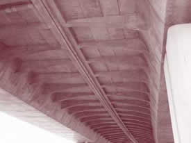 |
Figure 8. Furukawa Viaduct. (Photos courtesy of Sumitomo Mitsui Construction Co.)
The viaduct was built using the span-by-span method with an overhead truss, as shown in figure 8b. A CIP joint is provided between the span segments and the pier segments at both ends of each span. The longitudinal external post-tensioning is located inside the box to permit easy maintenance and replacement. The tendons were stressed in several stages. Precast, prestressed concrete deck panels span longitudinally between the transverse ribs, as shown in figure 8c. A CIP topping, which is transversely post-tensioned, is used to complete the system. A second feature to reduce the weight of each segment and to increase durability was the use of concrete with a specified concrete compressive strength of 60 megapascals (MPa) (8,700 pounds per square inch (psi). A photograph of the underside of the completed bridge is shown in figure 8d. Because this was the first application of this method, a full-scale test was performed for each construction phase to ensure safety. This superstructure design concept allows for future deck removal.
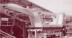
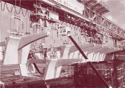
The Arimatsu Viaduct consists of two side-by-side, six-span continuous steel box girder bridges with orthotropic decks and runs above Route 23. The viaduct, with three lanes in each direction, has a length of 655 m (2,150 ft) and a weight of 12,000 t (13,200 tons). The longest span length is 130 m (427 ft). The substructure for the viaduct is similar to that of the Aritas Expressway. The superstructures for both bridges were assembled on falsework in span-length increments at the end of the viaduct and launched longitudinally above Route 23, as shown in figure 9, using a special automated launching system. Each of the six spans had to be launched within a 12-hour window between 8 p.m. and 8 a.m. Both bridges were launched side by side.
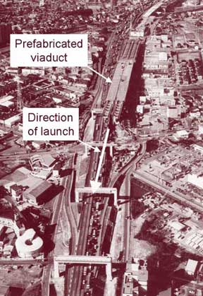
Figure 9. Arimatsu Viaduct. (Photo courtesy of Mitsubishi Heavy Industries.)
The automated launching system used a centralized control system to maneuver 100 jacks, including 56 synchronized jacks each with a 500-t (550 ton) capacity and a 230-mm (9-in) stroke. The synchronized jacks were used to control the up-and-down movement, left-to-right directions, and height differences. A course correction device was provided at each bent to maintain a gap of 40 mm (1.6 in) between the two bridges during the launch.
The bridge construction contract did not contain any financial penalties for not completing the launch in the designated time. The contractor, however, was required to absorb all additional costs associated with delays after the allowed time and was not allowed an additional traffic interruption without issuing a public notification 60 days before the closure. At the time of the team's visit, the contractor had completed every closure event on time.
The Yahagigawa Bridge is a four-span, composite hybrid steel and concrete cable-stayed bridge with corrugated steel webs constructed across the Yahagigawa River between Toyota and Togoto-Higashi Junction. The bridge consists of two pylons with an intermediate pier situated between the pylons to give span lengths of 173.4, 235, 235, and 173.4 m (569, 771, 771, and 569 ft). A single plane of stay cables is used. The portion of the hybrid superstructure supported directly by the cables consists of a 43.8-m (144-ft) wide five-cell box with top and bottom concrete flanges and corrugated steel webs. The portion of the superstructure above the central pier is a five-cell steel box girder. It is claimed to be the world's longest single span and total length prestressed concrete bridge with corrugated webs. The concrete towers, which are 109.6 m (360 ft) tall, are claimed to be the tallest concrete bridge towers in Japan. It is the first cable-stayed bridge in the world to use corrugated steel webs and steel box girders.
The use of corrugated steel webs is reported to have the following advantages:
Two extradosed bridges are located on the new Meishin Expressway across the Kiso River and Ibi River. From the exterior, extradosed bridges resemble cable-stayed bridges with short pylons, but the structural characteristics are more comparable to post-tensioned box girder bridges. The Japanese described the following features for extradosed bridges:
The Kiso River Bridge is a five-span bridge with four pylons and the Ibi River Bridge is a six-span structure with five pylons (figure 10). Both bridges use a single plane of cables, a concrete box girder for the cross section to which the stay cables are attached, and a steel box girder for the superstructure beyond the ends of the stay cables. One factor in the selection to use extradosed bridges was the need to complete all pile-driving and substructure work in one dry season from October to May. The use of extradosed bridges allowed for longer span lengths and fewer foundations.
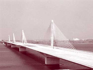
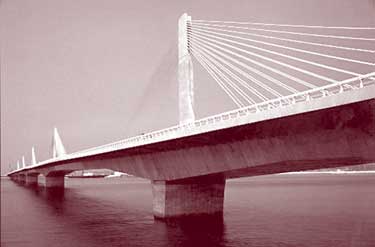
Figure 10. Extradosed bridges. (Photos courtesy of JHC.)
The Japanese economy is very dependent on the railway system for transportation of materials and people. About 50 percent of the Japanese population uses the railways each day. Consequently, any interruption to traffic flow must be minimized. In addition, working space is very limited alongside the railway lines in urban areas. For improvements on the Chuo Line at the Tokyo station, new structures were built alongside the existing railroad bridge and then jacked laterally into place. The Japanese also have found it feasible to incorporate temporary girders into permanent girders, as depicted in figure 11. A temporary bridge was first erected alongside an existing multiarch viaduct using span lengths equal to those of the original viaduct. Train traffic was diverted to the temporary bridge (figure 11a) while the original viaduct was demolished. The depth of the temporary girder was then increased by adding girders below the temporary girders. Formwork was then added (figure 11b) and the two girders were encased in concrete while the bridge was still in service (figure 11c). Finally, the new bridge was moved laterally to replace the previous viaduct. Intermediate piers were then removed so that the four original arches were replaced with a two-span bridge. This method reduced the period of railway service interruption, nighttime work with closed tracks, site work, and total cost.
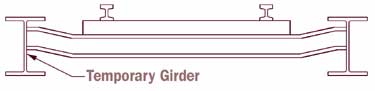
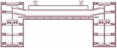
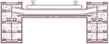
Figure 11. Use of temporary girders as part of the permanent structure. (Based on drawings by East Japan Railway Co.)
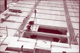
On the new Joban Line near the Kita-Senju station, segmental precast girders were used to construct a bridge for a new railway line between two existing lines while keeping the lines in service. The sequence of construction is shown in figure 12. After construction of the first two spans, the next girder was assembled on top of these spans (figure 12a). A temporary steel erection girder was then placed in the next span (figure 12b) and a suspension girder positioned above the span (figure 12c). The concrete girder was moved across the span on the erection girder and hung from the suspension girder (figure 12d). The erection girder was moved forward to the next span. The concrete girder was lowered into its final elevation (figure 12e). The concrete girder was moved laterally to its final position and the sequence repeated for a second parallel concrete girder. The whole process was repeated on the next span.
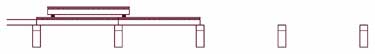
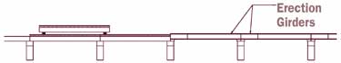
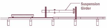
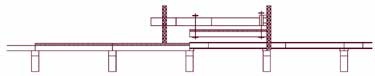
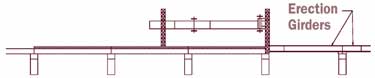
Figure 12. Sequence of construction on the new Joban Line. (Based on drawings by East Japan Railway Co.)
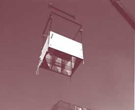
The Mitsuki Bashi (Three-Month Bridge) method is a quick construction system developed by Mitsui Engineering & Shipbuilding Co, Ltd., for roadway overcrossings in an urban area. The system includes a steel hull footing, a steel bridge pier and cap, and a steel box girder superstructure, as shown in figure 13a. In the first stage of construction, the steel hull footing is placed in an excavated foundation. The footing has a short stub pier on top and vertical holes through which piles can be driven. The system allows the piles to be placed through the steel footing while the steel pier and pier cap are being erected. The hull can then be filled with concrete to create a composite foundation. At the same time, the main span is being assembled offsite. The main span is moved into place as a single unit using a special transportation vehicle.
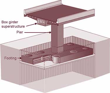
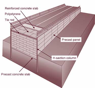
Figure 13. Mitsuki Bashi method. (Drawing courtesy of Mitsui Engineering & Shipbuilding Co.)
Construction of the approach portion of the bridge is depicted in figure 13b. First, H-section columns are driven alongside the final approach road location. Soil of the same dead weight as the approach portion is excavated. A precast concrete slab is placed between the columns in the excavated areas. Expanded polystyrene is installed above the slab and vertical precast panels are placed between the columns. Finally, a concrete slab and riding surface are placed on top. Although the system has not been used, the shortest estimated construction time is 3.5 months for a 400-m (1310-ft) long crossover at an estimated cost of $7 million.
The Chofu-Tsurukawa Overbridge, shown in figure 14, is a temporary bridge built in 11 months to eliminate a grade crossing causing traffic congestion. The requirements for the project included a short construction period, environmental restrictions, traffic restrictions, and future removal of the bridge. The bridge is a nine-span, continuous rigid frame, steel girder bridge with span lengths ranging from 8.0 to 26.0 m (26 to 85 ft) for a total length of 163 m (534 ft). Construction of the bridge involved the use of liquefied soil stabilization, precast concrete footings, rubber bearings beneath the column base to reduce seismic forces, steel piers, precast deck panels post-tensioned longitudinally on the approach spans, and precast concrete retaining walls. Environmental protection involved the use of a low-noise crane, drilled foundations instead of driven piles, multipulley pile extractor, and low-noise drift pins. The precast deck panels and retaining walls were installed at night to minimize traffic disruption. In the future, the railroad tracks will be placed below grade and the bridge removed. As a result of this construction, the travel time to cross the railroad has been reduced by 65 percent and the number of cars detouring to nearby roads has dropped by 20 percent. The economic benefit of the bridge is estimated to be about $10 million per year.
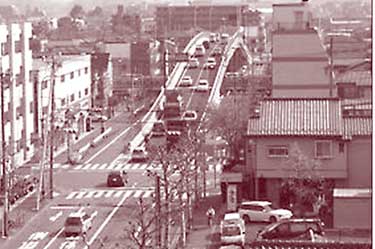
Figure 14. Chofu-Tsurukawa Overbridge. (Photo courtesy of Mitsui Engineering & Shipbuilding Co.)
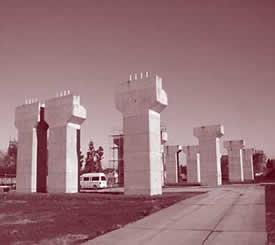
The Sumitomo Precast form for resisting Earthquakes and for Rapid construction (SPER) system is a method developed by Sumitomo Mitsui Construction Company for rapid construction of short and tall bridge piers in seismic regions using stay-in-place 100-mm (3.9-in) thick precast concrete panels as both formwork and structural elements. For short solid piers, panels with pre-installed cross ties, as shown in figure 15a, serve as exterior formwork. Segments are stacked on top of each other using epoxy joints and filled with cast-in-place concrete to form a solid pier (figure 15b).
 |
 |
 |
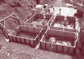 |
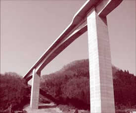
Figure 15. SPER method. (Photos and drawing courtesy of Sumitomo Mitsui Construction Co.)
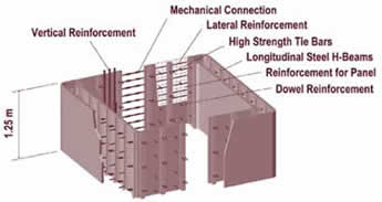
For taller hollow piers, inner and outer forms are used to produce a hollow section, shown in figure 15c. To reduce weight and size for hauling, panels form two channel-shaped sections. Lateral reinforcement is embedded in the channel sections and joined together in the field using couplers. Assembling channel-shaped forms in the field is shown in figure 15d. After inner and outer precast forms are set around vertical reinforcement, cross ties (transverse reinforcement) are placed and concrete is cast within the section. A completed hollow pier is shown in figure 15e. Use of high-strength bars for cross ties reduces congestion and fabrication time. Special details are used to transfer the force from the transverse reinforcement into the panels. Cast-in-place concrete is used to connect the piers to the superstructure.
The SPER system has been used on four bridge projects, including the Otomigawa Bridge in Ayabe City, Kyoto Prefecture, with pier heights of 15.6, 32.5, 51.1, and 32.5 m (51, 107, 168, and 107 ft). The system can shorten construction time to 60 to 70 percent of the time required for conventional cast-in-place construction for 10-m (33-ft) tall piers. This is attributed to the elimination of formwork and reduction in curing time. For 50-m (164-ft) tall piers, reduction in placement time for lateral reinforcement and cross ties resulted in a one-third decrease in construction time. Experimental research in Japan has demonstrated that stay-in-place forms develop composite action with the CIP concrete and that piers achieve a seismic performance comparable to conventional reinforced concrete piers. Use of high-performance concrete (HPC) panels results in a high-quality, durable external finish and an aesthetic appearance. A similar system reportedly has been developed by Kajima Corporation.
While traveling in Japan, the team noticed numerous uses of sound walls along the sides of highways and on bridges. Most sound walls appeared to be prefabricated of lightweight materials. A feature of many sound barriers on bridges was the use of transparent panels. This not only allowed the bridge user to see out, but also allowed sunlight to penetrate through so that the shadow of the bridge on the ground was not as big. At the same time, people on the ground could see the sky and sunshine through the panels. A sound barrier at ground level alongside the Furukawa Viaduct is shown in figure 16a. In some cases, the sound barriers formed complete tunnels, as shown in figure 16b.
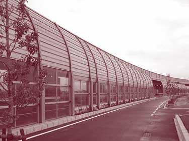
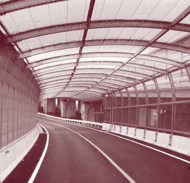
Figure 16. Sound barriers.
| << Previous | Contents | >> Next |