U.S. Department of Transportation
Federal Highway Administration
1200 New Jersey Avenue, SE
Washington, DC 20590
202-366-4000
Traditional means for capturing commercial motor vehicle (CMV) size include using a measuring tape and a measuring bar to manually determine and document a vehicle's size in three dimensions. Several shortcomings have been associated with these traditional methods. First, the task requires an initial subjective assessment by an enforcement officer to determine what measurements are required. Second, the process of capturing the measurements is time consuming, keeping an officer from performing other enforcement-related duties. Third, some aspects of vehicle size are difficult for the enforcement officer to physically or safely determine (e.g., the highest point of an irregular load). Lastly, as with any manual measurement process, the determination and documentation tasks are open to errors.
Despite these known shortcomings, only two of the six countries the scan team visited use some form of technology to improve commercial motor vehicle size enforcement: Switzerland and Germany. Slovenia, Belgium, and France reported using only traditional means for capturing vehicle size, including a measuring tape and a measuring bar. Typically, enforcement officers carry these instruments in self-contained mobile enforcing units or smaller police vehicles or they are securely stored at common mobile enforcement sites.
Although height-detection equipment is not yet in regular use, the Netherlands is experimenting with it, considering both gantry-mounted systems and joint height-detection/WIM systems with a focus on tunnel infrastructure. One early finding is that the best locations for height-detection systems (e.g., just preceding tunnels) do not often correspond to the best locations for WIM systems, so combined systems may not be cost effective.
As part of a larger system supporting an enforcement strategy for remote Alpine region tunnels, the Swiss have used infrared detectors to check vehicle height and variable traffic signals to provide adaptive control.(15)(16) Height sensors are placed upstream of tunnels. If the sensors identify a vehicle as overheight, a red light is activated indicating that the driver should divert.
Most recently and in an alternate application, Swiss cantonal police have used dimensional measuring devices in conjunction with their heavy goods vehicle (HGV) enforcement sites, which rely on laser scan technology (www.ectn.com/html/pdf/Profiler.pdf) to obtain a full three-dimensional profile of the vehicle (see figures 9 and 10). Tested for 2 years to ensure adequate performance, the vehicle profiler system is now used by cantonal police at four HGV enforcement sites in Switzerland: two in Zurich, one in Erstfeld, and one in Unterrealta.
Figure 9: Switzerland: vehicle profiler system.
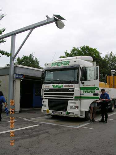
Figure 10: Switzerland: vehicle profiler system.
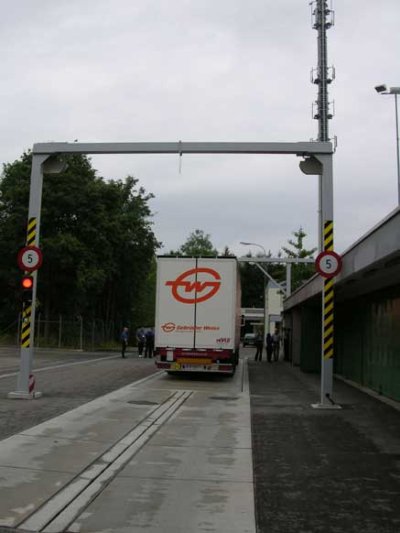
The Swiss have used the vehicle profiler system, in conjunction with static scales and at vehicle speeds less than 5 km/h (the maximum manufacturer-specified driving speed of the vehicle), for direct enforcement of commercial motor vehicle size since September 2005. System accuracy has rarely been challenged in court and has been readily defensible when called into question. The Swiss allow the following measurement tolerances when issuing citations from the vehicle profiler system: 5.00 centimeters (cm) for vehicle height, 4.00 cm for width, and 10.00 cm for length. No tolerances are allowed when measurements are taken manually. Swiss enforcement officers report overall time savings, greater accuracies, higher certainty in court, and the ability to process a higher volume of trucks. Despite these gains in efficiency, two officers continue to be used per site. The vehicle profiler technology has simply freed up officer time for other enforcement duties.
The vehicle profiler system is estimated to cost $250,000 as a stand-alone system. A facility similar to Swiss HGV enforcement sites, which include full gross vehicle weight static scales, is estimated to cost $700,000.
Germany is using a similar gantry-mounted vehicle profiler system as part of its Toll Collect system, but with a different application. Instead of using the vehicle profiler system at low speeds for direct enforcement of commercial motor vehicle size, the Germans measure vehicle size at high speeds to preselect potentially oversized vehicles from the traffic stream. If a vehicle is identified as potentially oversized, the driver is directed off of the main roadway for manual measurement and subsequent enforcement action.
The use of technology to support commercial vehicle weight enforcement varies among the countries visited on implementation and application extent (the COST 323 Project lent consistency to deployment site selection and accuracy determination through development of a European WIM specification). A general consistency, however, was noted in the type of WIM sensor (i.e., piezoquartz or piezoceramic) used for roadway applications, and the countries are addressing previously observed challenges with accuracy and maintenance. Piezo-based systems have several advantages, including lower procurement, installation, and maintenance costs with limited disruption to traffic during installation. As such, these systems can be more widely implemented, providing greater geographic coverage for enforcement and data collection. Bridge WIM systems are also generating interest in several of the countries visited.
Emerging technologies are focused on fiber optic-based, high-speed WIM systems and the use of multiple-sensor WIM to achieve sufficient per-truck accuracy levels to support direct, automated enforcement of commercial vehicle weight limits. Existing accuracy levels attained by WIM systems are sufficient for preselection of vehicles to weigh on static scales for enforcement and for planning and statistical purposes, but are not sufficient for direct, automated enforcement.
Calibration procedures mimic those in the United States:
Recently, the Netherlands developed a dynamic calibration vehicle that eliminates traditional dynamic-to-static measurement adjustments, particularly for multiple-sensor WIM installations.
Slovenia has emerged as a leader in the development of bridge WIM system technology, which relies on the instrumentation of existing roadway structures (i.e., bridges, culverts). In brief, bridge WIM systems use strain transducers (or strain gauges) to capture bridge deflection measurements under moving loads. Axle measurements can be captured through traditional portable or permanent axle sensors or through Nothing-on-the-Road (NOR)/Free-of-Axle Detector (FAD) systems, which require no axle sensors on the road surface.
In the early 1990s, early prototypes of bridge WIM systems were developed independently in Slovenia and Ireland. Bridge WIM systems were considerably enhanced through the COST 323 and WAVE Projects, with bridge WIM projects concentrated in Slovenia, Ireland, France, and Germany. Before these efforts, knowledge was based on U.S. experiences with bridge WIM in the late 1970s, but the cost and insufficient sophistication of software driving those early systems likely contributed to their lack of popularity. More recent efforts, however, resulted in:
In 1999, the Slovenian National Building and Civil Engineering Institute (ZAG) partnered with Cestel, a private manufacturing company, to commercialize the SiWIM prototype. Today, more than 60 SiWIM sites are fully operational in Slovenia, Sweden, France, the Netherlands, Croatia, and India. In Canada, Denmark, Austria, and Hungary, SiWIM is used in a more limited application.
Figure 11: Slovenia: bridge WIM system.
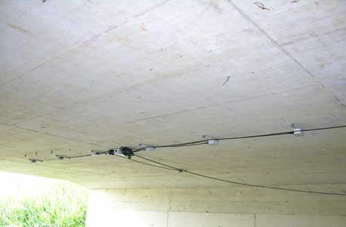
Figure 12: Slovenia: bridge WIM system.
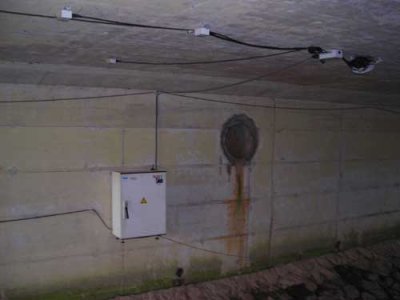
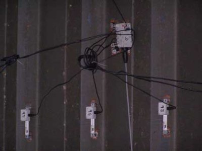
The SiWIM system operates as follows: As a vehicle passes over the bridge, a series of strain transducers, mounted below the bridge and invisible to the vehicle driver, measures the vehicle's "weight" as a voltage output from the transducer (see figures 11 and 12). This voltage measurement is not transformed to strain measurement units. The signals from each sensor (typically 16 sensors per two lanes of traffic) are amplified and converted from analog to digital. All are stored in a file and used to support system calculation of axle loads, axle spacing, gross vehicle weight, etc. The transducers are self-temperature compensating to enhance accuracy. In addition, the system includes input for up to five thermocouples that measure the temperature of the structure and compute applicable correction factors. The system can be equipped with a camera to capture a video image of each vehicle crossing the bridge (see figure 13). The video image and weight data can be transmitted to enforcement officers in support of a downstream enforcement site (enforcement officers use handheld or portable computers equipped with General Packet Radio Services (GPRS) for IP packet transmissions and Windows® CE operating systems) if mobile enforcement activities are underway or stored for later use.
Figure 13: Slovenia: bridge WIM system.
The SiWIM data acquisition system differs from typical modular data acquisition systems in that custom software to perform the vehicle classification analysis resides on the system, not on the PC. Data are stored in a temporary queue. When a transducer meets trigger conditions, the system looks back in the queue a sufficient period of time to find a pre-event voltage reading. That reading becomes the "zero" reading and is subtracted from subsequent readings for that event. A new "zero" voltage is established for each weighing event, essentially eliminating concerns about gauge drift. The SiWIM-E (engine), developed on a Microsoft® Windows® NT platform, is the heart of the SiWIM system. SiWIM-F (front end) software is used to configure and calibrate the system, calculate influence lines, monitor the operation of the system, and transfer the data. SiWIM-D is a stand-alone Windows-based application that provides additional reporting features such as gross vehicle and axle load histograms and overloading summaries.
For weight accuracy, the SiWIM system achieved Class B(10) accuracy levels, and sometimes A(5) to B+(7) for some criteria, when installed on a simply supported reinforced concrete slab bridge 5 to 10 meters (m) long. Weight accuracy for the SiWIM system for other bridge types is under investigation inside and outside Slovenia (e.g., results in Canada prove that beam bridges are suitable for NOR installation with B(10) accuracy levels attained and approved). In general, bridge WIM weight accuracy depends on:
The optimum bridge span for WIM applications is 5 to 10 m, although bridge spans of 2 to 20 m are acceptable.
For vehicle classification, the NOR/FAD systems capture more than 95 percent of all axles on stiff slab bridges, but misclassify some of the vehicles. A self-correcting module is under development to improve this accuracy. NOR/FAD systems show more success on beam-deck bridge types; ZAG reports the system classifying 261 instead of the true 260 vehicles classified. If reasonable accuracy can be achieved for additional bridge types, NOR/FAD systems provide several benefits, including improved durability, easier installation, no traffic delays, and invisibility to the motoring public.
The Slovenian SiWIM system is calibrated using pre-weighed trucks or comparative data from static scales for sampled trucks from the traffic stream. The COST 323 European specification states that 60 percent of the calibration runs must be made at the prevailing traffic speed, 20 percent at higher speeds, and 20 percent at lower speeds.
The hardware components of the SiWIM system do not reflect significant advancements in technology. Instead, potential benefits of the SiWIM system include the ability to develop calibrated influence lines; the system-based, rather than PC-based, functionality; and the system's portability and minimal impact on traffic. A drawback of the system is its use of noncalibrated transducers, which limits the value of WIM data for later structural assessments. Under the existing design, transducers must be calibrated to produce strain data. Minimal effort may be required to transform the existing voltage readings into strain measurements when the data are collected. This feature would simplify the use of WIM-generated data, enhancing the system's attractiveness for structural or bridge engineers. An additional drawback is that bridge WIM systems in general require a suitable bridge located where weight measurements are also desired.
Historically, Switzerland has focused on the development and testing of WIM systems rather than on their deployment and use. A number of WIM systems were installed at the Hagenholz ETH test facility near Zurich. In a large-scale COST 323 test, six WIM systems and four additional sensors were installed and monitored on an urban roadway in Zurich. Gross weights from thousands of statically weighed vehicles were used to determine the levels of accuracy for each system; the accuracy of axle weights was not tested.(17) The Swiss also participated in the TOP TRIAL Project, with test sites in Germany.
Concurrently, a Swiss company, Kistler, developed a quartz-based piezo sensor that demonstrated the following advantages:
Initial performance results from the Hagenholz test site were positive and led to further implementation and testing in Europe, the United States, and other locations worldwide. Some of these initial deployments in Europe and the United States experienced durability problems, resulting in high piezoquartz sensor replacement rates between 1995 and 2005. Kistler reported that the new generation of sensors resolved the durability problem.
In all new Swiss installations of WIM facilities, piezoquartz technology is deployed exclusively. Typically, two sensors are configured 7 m (23 feet (ft)) apart in each lane, although the use of alternate arrays is being explored. While the selection of technology is consistent, the level of deployment within the country varies. Each canton is responsible for implementing and using WIM systems. The Swiss Federal Roads Authority (FEDRO) does not and will not mandate their use.
Despite the reported higher accuracy and increased reliability of the Kistler WIM sensors, cantonal police continue to use traditional static scales (e.g., platform scales, weigh bridges, axle load scales, and wheel load scales) to enforce commercial motor vehicle weight and WIM systems only for preselection. The dynamics of the vehicle (i.e., suspension, load, acceleration, wind) lead to higher-than-desired standard deviations of measurements from WIM systems. In addition, frequent snowfall challenges the accurate capture of data from WIM systems because vehicles cannot distinguish designated lanes during snowfall.
The Swiss report low maintenance with their WIM facilities. The sensors must be inspected periodically (annually) for wear. Calibration is also performed annually, using about 15 staff members for 1 to 2 days per year (i.e., about 120 to 240 person-hours). Calibration assessment and analysis are conducted in accordance with the COST 323 European specifications. About 40 to 50 vehicles in excess of 3.5 metric tons are diverted from the local traffic stream to be statically weighed. Data measured at the static site include number of axles, distance between all axles, distance from front of vehicle to first axle, distance from last axle to rear of vehicle, overall length, individual axle load, and overall weight. In addition, a photo is taken of the vehicle. Static measurements are relayed to personnel at the WIM site using unique vehicle identification information to allow for immediate adjustments.
Historically, Germany has conducted and participated in research to improve the accuracy of WIM systems, participating in both the COST 323 and WAVE Projects. In the early 1990s, the German Federal Highway Research Institute (BASt) conducted studies to investigate the performance of various systems, including a Golden River capacitance strip sensor, an ECM piezoelectric sensor, and a PAT bending plate system. During this same time, the TOP TRIAL Project, with four participating countries (Germany, the Netherlands, Portugal, and Switzerland), was initiated to:
The test site was established along the motorway A9 near Bavaria using staggered multiple-sensor WIM systems. Most recently, Germany has been investigating the performance of an integrated matrix (IM) WIM sensor.(18)
Based on the results of these early tests, Germany began installing bending plate WIM technology in the Rhein-Main area.(19) By 1999, more than 15 WIM systems were installed. In 2000, Germany commissioned a Swiss-based company, Kistler, to install its piezoquartz WIM sensors at 13 WIM stations. Today, Germany has a network of about 40 WIM systems, using both bending plate and piezoquartz sensor technology.
The current WIM sites are used for both preselection for weight enforcement and statistical data gathering. WIM systems are commonly installed in the right lane or right two lanes only with traffic sensors (i.e., electronic loops) installed across all lanes. This layout strategy significantly reduces capital installation costs while still capturing weight data for an estimated 80 percent of the heavy traffic.
BASt researchers concluded in earlier investigations that WIM systems, regardless of sensor design, needed periodic, independent calibration and recommended calibration at least twice per year. The calibration of WIM systems can be maintained by monitoring the axle load distribution for each site, although the distribution varies from site to site. Additional calibration checks were recommended whenever axle-weight distributions at a site change.(19) Current calibration procedures use two trucks of known weight—half loaded and fully loaded—performing 15 runs each.
The recent Toll Collect system includes 300 "toll checker" gantries strategically located throughout the country and equipped with infrared (IR) detection equipment and high-resolution cameras able to profile trucks and record number plates. These gantries do not include any weight capture capabilities (e.g., WIM). WIM installation would have greatly increased the cost of the system and was not required to support the German toll schedule, which relies on a truck's weight capacity rather than observed weight. Integration of WIM would allow real-time weight-distance tolling, but is not currently being used in Germany.
In the Netherlands, WIM systems began to generate significant interest only when groups other than the pavement design and maintenance community became interested in the information available from these systems. As recently as 1996, no operational WIM systems were in use, although several systems had been purchased from various vendors for testing. At that time, plans were to install 40 to 60 WIM sites, with the first five installations occurring in 1997.(3)
Funded through the Ministry of Transport, WIM installations are prioritized and must compete with other transportation needs of the nation. As of 2006, the Dutch reported only six WIM system installations nationwide, concentrated around the Port of Rotterdam along the major motorways. Two WIM system sites were under construction. Like many of the other countries visited, the Netherlands uses Kistler piezoquartz sensors, but has experienced some problems with durability, attributable partly to the porous asphalt design of its roads.
Despite their limited deployment of WIM systems, the Dutch have made significant advancements in technology performance and its use in automated enforcement, participating in the COST 323, WAVE, and TOP TRIAL Projects. In recent studies, including the WIM-HAND and WIM-HAND2 Projects (described in the "Fully Automating CMV Size and Weight Enforcement" section of Chapter Three), the Dutch have focused on the use of high-speed, multiple-sensor WIM systems to achieve the required accuracy levels to support automatic enforcement of overloading. In addition, these efforts have focused on defining procedures for acceptance of WIM systems intended for use in automatic enforcement. Key issues are accuracy, certainty of the measurements from the WIM system, reliability of the acceptance test, and use of static axle loads as an accepted reference.(20,21)
As part of these latter efforts (i.e., WIM-HAND and WIM-HAND2), the Dutch constructed a specially designed calibration vehicle (see figures 14, 15, and 16). Because metrological laws and specifications are based on static weight, typical calibration methods for WIM convert dynamic loading to a static measure. Ideally, every sensor should be reading the most accurate dynamic load possible rather than correcting to an average static value. No such vehicle was available to calibrate the dynamic measure to the true dynamic load. The newly designed Dutch calibration vehicle measures, while driving, the dynamic forces exerted on the WIM system by the measurement axle. The calibration vehicle compares its own measurements with those of the WIM system integrated into the road. During the design phase, the most important requirements for the calibrating vehicle were the following:
Figure 14: The Netherlands: dynamic calibration vehicle.
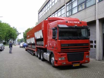
Figure 15: The Netherlands: dynamic calibration vehicle.
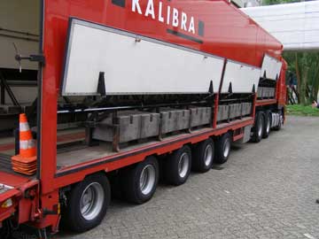
Figure 16: The Netherlands: dynamic calibration vehicle.
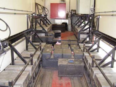
The calibration vehicle was commissioned by the Road and Hydraulic Engineering Institute of the Dutch Ministry of Transport, Public Works, and Water Management. Kalibra International built the vehicle, while TNO Automotive provided the measuring technology.
The calibration vehicle has a special exemption allowing it to travel with higher axle loads and at higher speeds. Since WIM systems are not calibrated more than a few times per year, the calibrating vehicle is used to calibrate traditional static weigh bridges the rest of the year.
The Slovenian bridge WIM system (SiWIM) is being tested in the Dutch highway environment. A bridge WIM system was recently installed along the A-4 highway from Amsterdam to Den Haag. The purpose is to test equipment performance under severe Dutch highway conditions. Measurements from the bridge WIM system will be compared to WIM system measurements from a conventional installation a few kilometers upstream from the bridge site and, when possible, static measurements resulting from control activity performed by the National Police.
Belgium participated in both the COST 323 and WAVE Projects, though to a lesser extent than some other project partners. The Belgian Road Research Center (BRRC) conducted the analysis for the Continental Motorway Test (CMT) and the Cold Environment Test (CET), which were intended to determine the reliability and accuracy of marketed high-speed WIM systems under variable traffic and climatic conditions. The test sites were near Metz, France (CMT), and Lulea, Sweden (CET).
Belgium relies predominantly on the use of static or low-speed WIM systems for enforcement. The Walloon Region is the only region in Belgium actively deploying high-speed WIM systems. At the time of the scanning study, six Electronic Control Measure (ECM)™ piezoceramic WIM systems were in operation. These systems are used predominantly to collect data for statistical planning purposes rather than for preselection for weight enforcement. Although some systems attained A(5), B+(7), or B(10) accuracy levels using the COST 323 procedures, other systems were only able to attain between C(15) and D(25) accuracy levels for gross vehicle weight. These latter accuracy classes show sufficiency for statistical planning purposes only. Site conditions (i.e., less-than-ideal road environments) at these locations were thought to affect the accuracies observed.
Other challenges associated with these systems were reported as follows:
The initial manual calibration was performed using three preweighed test vehicles typical of the local traffic stream. At least 10 passes per vehicle were performed, with at least five passes per vehicle performed a minimum of 2 weeks later for validation purposes. The systems (including devices and communications) are maintained annually. Calibration is performed using preweighed test vehicles.
Nationwide, France uses 170 WIM systems to collect weight data and provide statistical planning support through the SIREDO (Système Informatisé de REcueil de DOnnées) Network.(22) These systems rely largely on automatic self-calibration and a comparative review of static weight data (captured during enforcement activities) to meet data quality requirements. The combination of autocalibration and static weight data comparative procedures has eliminated the need for resource-intensive manual calibration conducted typically on an annual basis.
Historically, the French have been actively involved in advancing the accuracy of WIM equipment (since the late 1970s) and have conducted several notable field studies as part of the COST 323 and WAVE Projects:
As part of the WAVE Project, the French examined fiber-optic strip sensors to improve WIM technology at two separate test sites: along RN 10 near Trappes and at the Alcatel plant in Saintes. Fiber-optic cable technology was proven to have several advantages, including good metrological accuracy and low temperature dependence, operation capabilities in both static and high-speed conditions, electromagnetic immunity, timesaving installation, near real-time processing, and future capabilities of capturing tire pressure, vehicle acceleration, and other dynamic effects.(8)
Historically, the French have focused on the use of high-speed, multiple-sensor WIM systems to achieve the required accuracy levels to support automated enforcement of overloading. Using a multiple-sensor WIM site on A31, French researchers are investigating the effects of individual axle sensor accuracy, static weight estimation algorithms (SAve, SR, or ML1/2), and array design (~ 5–15 piezoelectric bars) on overall system performance.(25) The minimum required accuracy to achieve automated enforcement is estimated at A(5), according to COST 323 European specifications.
In addition to continued testing of multiple-sensor WIM systems, two prototype VIDEO-WIM systems were installed and are being used for:
Direct enforcement occurs at various fixed static enforcement sites or through mobile enforcement activities, although the final objective of these prototype systems is aimed at fully automated enforcement.
As part of the VIDEO-WIM system evaluation, two different WIM systems provided by ECM and STERELA were tested.(26) The ECM system is located along RN83 in the south-north direction about 6 km away from a static weighing area. The STERELA system is located along A31 in the north-south direction. In each case, only one lane was equipped with piezoceramic sensors. Other system components included electromagnetic loops for vehicle detection, monochromatic high-definition video camera and license plate recognition software, a local processing unit, and communications to transmit data. Neither system performed initially to the accuracy levels expected. The ECM system achieved C(15) accuracy for single axles and D+(20) accuracy for axle groups, using the COST 323 European specifications. For the STERELA system, the accuracy for axles in a group reached B(10) accuracy, while single axles and axle groups achieved C(15). Gross vehicle weight accuracy reached only D+(20). This underperformance on accuracy was attributed to the poor road structure at each site. Despite the compromised accuracy, the efficiency of the systems was proved, resulting in significant benefits for preselection. A total of 81 percent and 100 percent of the trucks stopped for static measurement were confirmed as overloaded, respectively, and 64 percent and 67 percent of these overweight trucks were fined based on the degree of overload, respectively (a 5 percent tolerance is allowed before a fine is implemented).
The success of these two prototype VIDEO-WIM systems has resulted in a call for tender, won by STERELA, to implement 10 to 40 similar systems throughout France. The final number of sites implemented will be determined by available funds. Any less than 10 sites results in system development costs that are too high. The systems will use high-speed WIM for preselection and either static or low-speed WIM for enforcement. Other specifications include the use of two strip sensors of unspecified technology but capable of achieving a minimum of Class C(15) accuracy; 1.6- to 4-m spacing between sensors (France typically uses 1.8 m), depending on pavement quality, sensor type, etc.; a communication link between the prescreen site and enforcement area; and a second video camera a minimum of 200 m downstream of the WIM video to allow for vehicle speed measurement and calculation.
Unique to France is its focus on low-speed WIM as an opportunity to move toward automated enforcement (in both Belgium and Switzerland, vehicles are allowed to roll over static scales at very low speeds (5 km/h), but it is unclear whether any adjustments have been made to the weight capture algorithms to reflect this "dynamic" weight measure or what legal or metrological changes were required to support this practice). The accuracy of these systems is typically A(3) to A(5), according to COST 323 European specifications, which complies with enforcement requirements. France has recently received approval for legal metrology of low-speed WIM and is now working to change the law allowing direct citation issuance based on low-speed WIM measurements. Until the law is changed, portable static scales must be used for citation issuance. The use of low-speed WIM will allow enforcement officers to process up to 10 times more vehicles, even with vehicle speeds constrained to less than 10 km/h. A tolerance of 5 percent is now provided for portable static measurements. The same tolerance will be used for low-speed WIM measurements.
To bring together these three technology applications—video-based preselection systems, multiple-sensor WIM, and low-speed WIM—a test site is being developed to perform efficient overloading controls while developing future automatic systems for enforcement. The automatic overloading control test site will be located along the RN4 between Nancy and Paris (Maulan and Rupt-aux-Nonains). The preselection system will be modeled after the two prototype systems described previously along RN83 and A31. The multiple-sensor WIM system (to be located in Maulan) will consist of a 16 piezoceramic sensor array, two wheel transverse location detection systems (to account for wheels passing too closely to the WIM sensor edge and to apply correction factors due to the transverse sensitivity of the sensors), and a temperature sensor. The low-speed WIM system will be installed at a newly constructed rest area at Rupt-aux-Nonains. Variable message signs (VMS) and bicolored (red and green) lights will direct approaching and onsite drivers, depending on their status (i.e., suspected overloaded, confirmed overloaded, etc.). A video camera with license plate recognition capabilities will allow for complete automated enforcement of commercial motor vehicle weight.
France is also testing the Slovenian bridge WIM system (SiWIM) on alternative bridge structures. Previous tests determined that the SiWIM system could achieve C(15) accuracy for a short-span integral concrete bridge (along RN4, Rosay-en-Brie) and B(10) accuracy for another short-span integral concrete bridge (along RN19, Nogent-sur-Seine) with better road smoothness. France is now testing this system on orthotropic steel bridge structures (see figures 17, 18, and 19). Unlike concrete bridge behavior, orthotropic structure behavior is locally independent of span length. Early challenges relate to installation; the strain transducers used in the SiWIM system do not adequately adhere to steel. The transducers were initially glued directly to the steel. Instead, the transducers could be secured to metal plates using screws, which are then affixed to the steel structure. The use of strain gauges could also overcome this issue.
Figure 17: France: bridge WIM system test site.
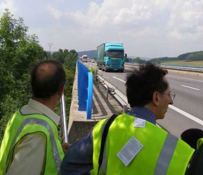
Figure 18: France: bridge WIM system test site.
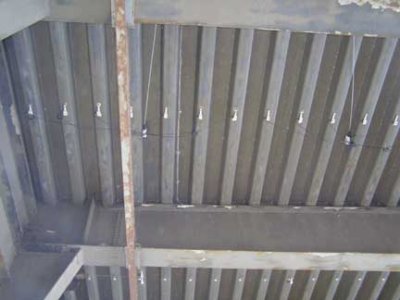
Figure 19: France: bridge WIM system test site.
In general, the use of technology for enforcing both commercial motor vehicle size and weight was viewed as beneficial in enhancing effectiveness and efficiency. For vehicle size enforcement, technology was also purported to improve the accuracy of dimensional measurements. Motivated by a desire to ease the burden of enforcement officers, representatives in many of the countries visited expressed a desire to see the use of technology for commercial motor vehicle size and weight enforcement increase.
Few wholly new technologies for commercial motor vehicle size and weight enforcement were observed in the countries visited. One exception is the automated vehicle profile measuring device used in Switzerland and Germany. No such technology is known to be in use in the United States for commercial motor vehicle size enforcement.
Many technologies observed for weight enforcement, while not wholly novel to the United States, offer enhancements in application that are new to this country. For example, software enhancements available through the SiWIM system, particularly the ability to develop calibrated influence lines, may make bridge WIM systems a more attractive tool than when first introduced in the late 1970s. Also, using multiple WIM sensors instead of a single sensor to achieve sufficient per-truck accuracy levels has not been widely pursued in the United States. Low-speed WIM, used in early preselection efforts in the United States, is seeing renewed application in the countries visited as a step toward automated enforcement.
| << Previous | Contents | Next >> |

