U.S. Department of Transportation
Federal Highway Administration
1200 New Jersey Avenue, SE
Washington, DC 20590
202-366-4000
The visit to Italy on June 23 through June 26, 2002, focused on meetings with foundation designers, contractors, and construction equipment manufacturers. In Cesena, the Trevi Group, specialists in international foundation engineering and a foundation equipment manufacturer, was the host for a program that included:
Figure 13. Secant piles used for excavation and wall construction in the Trevipark
The second stop was in Turin where the group met with representatives from the Rodio Corporation, an international geotechnical construction firm, headquartered in Milan. Rodio is currently working on the new Italian metro in Torino and a section of the high-speed rail line being constructed from Milan to Naples. The Rodio program included:
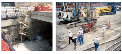
Figure 15. Turin subway project site visit showing: (a) station excavation and (b) continuous diaphragm wall construction.
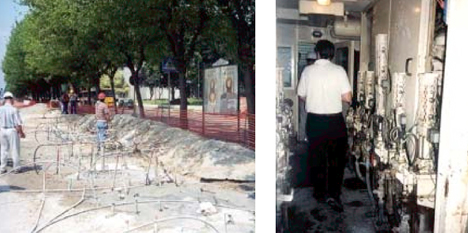
Figure 16. Turin subway grouting project site visit showing: (a) grouting and
(b) grout pump station.
The last meetings of the Italian tour were held in Milan at the offices of Impregilo/ S.G.F. S.p.A., one of the world’s largest international contracting firms that was formed by merging three companies specializing in the infrastructure, building construction, and environmental fields. The meeting included:
| DESIGN MOMENT | SURVEY PHASE | Analysis of existing natural equilibrium | CONSTRUCTION MOMENT | OPERATIONAL PHASE | Application of the stabilization instruments for controlling deformation response |
| DIAGNOSIS PHASE | Analysis and prediction of deformation response in the absence of stabilization measures | MONITORING PHASE | Evaluation and measurement of deformation response as the response of the rock mass during tunnel advance (measurement of extrusion at the face and convergence at the control of the cavity at varying distances from it inside the mass of the ground) | ||
| THERAPY PHASE | Control of deformation response in terms of stabilization system chosen | FINAL DESIGN ADJUSTMENTS | Interpretation of
deformation response
Balancing of stabilization systems between the face and the perimeter of the cavity |
Several technologies were reviewed with respect to accelerated construction for lateral excavation support and/or vertical foundation support, including:
Other important issues reviewed included a European requirement for all contractors and designers to have ISO 9000 series quality certification programs in place. Contractor warrantees for up to 10 years are also not unusual.
The following section provides a review of the accelerated construction methods identified in Italy in relation to the amplifying questions.
The CSP technique was developed as a rapid construction method for continuous cantilever walls. The cantilever wall provides high-capacity vertical and lateral earth support and could have applications for bridge support in cut situations and for cut embankment support and temporary excavations. The CSP system is constructed using augers housed inside a casing to make the excavation. The auger and casing are driven by two independent rotaries to optimize spoil removal and casing of the hole.
Intersecting columns are formed, which are up to 5 ft (1.5 m) in diameter and up to 87 ft (26.5 m) [66 ft (20 m) cased] in depth. Two micropiles per CSP may be drilled to increase vertical capacity. Excavation of the piles is performed without bentonite mud regardless of the kind of soil or the presence of water table. The technique does require specialized equipment that is patented, but several types are available from different suppliers and the equipment is readily available in the United States. The process is not patented. Design is conventional, relatively mature, and is currently done in the United States; however, the design procedure is not addressed in AASHTO specifications. CSP can be designed for seismic forces where needed. Italy has high seismicity in the north and south, and the system has been used in both regions. The scan team also had a significant interest in the potential use of CSP techniques for installation of individual bridge piles.
The production rate for a 3-ft- (0.9-m-) diameter pile was reported to be 413 ft (126 m) per day. It is efficient for large circular excavation (e.g., Trevipark, an underground silo-type facility constructed for an automated parking garage using CSP). A general bridge/foundation contractor with CSP equipment can install the system. Only nominal training would be required for experienced personnel. It is the scan team’s opinion that inspectors can readily inspect pile diameter, depth, and materials used in construction. Rotating out the casings as is done in this technology appears safer than the conventional procedure of pulling out pile or drilled shaft casings with a crane. The system has low noise and vibration. It is not affected by the weather, except as associated with delivery of the concrete.
CSP technology is contracted under performance-based contracts. Design-build contracting is also used (e.g., engineering and construction personnel from one of the scan team’s hosts, the Trevi Group, indicated that they do design-build on a regular basis). In these types of contracts, both performance based and design-build, the owner usually retains 5 to 10 percent of total billings as a warranty. If problems arise, the contractor is required to fix the problems. Research on this technology has been sponsored by the industry. The team’s host, the Trevi Group, spends US$6 to US$8 million dollars a year on research and development (approximately 2 percent of its yearly company intake). The Trevi Group provides a complete transfer of knowledge of the technology.
CDW is a technology for forming cut-off walls for excavation support, or vertical support using simultaneous excavation and concreting. As indicated in the developer’s presentation (the Trevi Group), the diaphragm wall is formed by excavating the soil with a special cutting module. The module is inserted into the soil and dragged along the extension of the diaphragm wall. The diaphragm wall’s thickness and depth are defined by the width and length of the cutting module. A template is used for proper alignment. First, the module is inserted into the soil until it reaches the final level of the diaphragm wall and, subsequently, it is shifted along the extension of the diaphragm wall. Concrete is poured into a plastic slip-form placed in the excavation immediately behind the cutting bar. The weight of the concrete provides an additional driving force against the cutting bar to facilitate excavation. This driving technique is particularly useful in cases of headroom restrictions.
The continuous placement of concrete during excavation precludes the use of slurries or other excavation-support techniques. The excavation method does not require the use of bentonite mud, even in the presence of cohesionless soils under the water table. A conveyor belt is used to dump the trenched material directly onto the truck and therefore provides a free and clean working area. The absence of joints makes the continuous wall safe from possible hydraulic sealing problems. The diaphragm wall may be reinforced by inserting steel piles into the newly concreted wall sections.
In situations where the headroom is low, e.g., with 20 ft (6 m) of headroom, a wall up to 33 ft (10 m) deep can be constructed. Production rates of 110 to 160 sq ft (10 to 15 sq m) per hour of completed diaphragm wall have been achieved. The maximum wall depth is 45 ft (15 m).
CDW does require specialized equipment. The equipment is patented, but several types and suppliers are available; however, the equipment is not currently available in the United States. The process is not patented, and design is based on conventional diaphragm walls. Only the construction technique is unique. The best application and production appears to be for temporary bracing or diaphragm cut-off walls in low headroom situations. For depths beyond 23 ft (7 m), concrete pressures need to be carefully monitored. This technique apparently does not work well for clean sand. In the scan team’s opinion, QA/QC would be similar to typical diaphragm walls (depth and width). The scan team also believes that specific training and experience for operators and technicians is needed. Weather does not appear to be a problem, except when the delivery of the concrete is affected.
Performance-based contracts are typically used for CDW technology. Our hosts again indicated that they are being regularly contracted on a design-build basis. The owner usually retains 5 to 10 percent of the total billings as a warranty. If problems arise, the contractor is required to fix problems (presuming that issues concerning differing site conditions are not precluded).
Reinforced Protective Umbrella Method (RPUM) is an accelerated construction method for soft ground tunnel excavation support, and was identified by the scan team as having potential for applications in bridge and embankment excavations. The RPUM system entails the execution of subhorizontal consolidation works along canopies around the section to be excavated, preventing caving during excavation and minimizing the deformation behavior of the tunnel by redistributing the stresses on the supports. The components of the system include forepolings, jet-grouting columns, and fiberglass nailing.
The fiberglass nails are installed as forepoles around the tunnel walls and behind the tunnel face and allow excavation directly through the stabilized nailed section. Nails are drilled in at a rate of 223 ft (68 m) per hour. This rapid drilling rate allows up to 100, 72-ft- (22-m-) long fiberglass nails to be installed and grouted in 32 hours. The tunnel is cut using automated controls equipped with 27 sensors that control the position of the blade and cutting force of the equipment. The tunnel can be advanced at a rate of 7 ft (2 m) per day, including consolidation, temporary support, and liner. Since the application is internal, weather is not a problem. This technology provides maximum safety conditions—excavation proceeds under the concrete lining. The scan team is uncertain if this method is actually faster, but it was reported to allow for consistent progress and an easier cash flow forecast.
The RPUM technology requires specialized equipment, which is patented. It was apparent to the scan team that specialized experience and training are required to operate this equipment. Several types of the equipment are available in Europe and the United States. The process is not patented. It is suitable for tunneling in rural and urban areas. Specialized design-build tunneling contractors currently use this technology. Performance-based contracts are usually used with the owner retaining 5 to 10 percent of total billings as a warranty. If problems arise, the contractor fixes them.
Pretunneling is another accelerated soft ground tunneling method that the scan team identified as having potential in other embankment and bridge excavation applications. Pretunneling is a new, advanced method for the construction of large section tunnels. In pretunneling the final load-bearing structural lining of the tunnel is constructed first, before the soil excavation, without first-phase consolidations ribs and shotcreting. The concrete shells are built by excavating the soil using a suitable cutting module. The equipment and excavation techniques are similar to CDW. The cutting module is initially inserted into the soil like a blade, excavating the soil at its frontal section. The concrete is simultaneously pumped into a slip-form to fill the cavity left by the cutting module. The module is then shifted transversally following the vault section.
This technology may be used to widen existing tunnels and to construct final tunnel lining before excavating the soil. Blade size and boulders will pose a problem with this technique. Since the technique is performed inside a tunnel, weather is not a problem. It is unclear to the scan team if this technique is actually faster than conventional tunneling methods; however, it clearly appears to be safer. Specialized, patented equipment, which is required for this technology is available, however, not in the United States. As with RPUM, specialized design-build contractors use this technology.
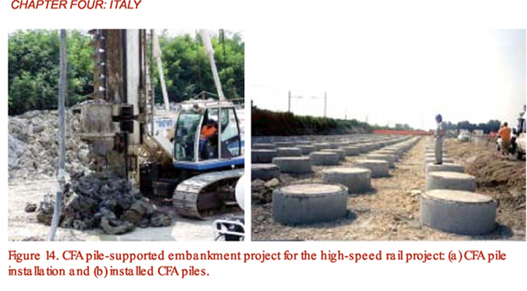
CFA piles provide a method for rapid installation of vertical or slight batter piles for soil or foundation support. As the name implies, a CFA assembled on a central hollow pipe is used. The auger is rotated into the ground removing a minimum of soil. At completion of boring operation, the auger is extracted while concrete is pumped through the internal hollow pipe. Concrete with a maximum aggregate size of 0.6 in (15 mm) and a slump value higher than 9 in (220 mm) is required. The steel reinforcement cage is finally lowered (or sometimes helped with static or dynamic vibration) into the fresh concrete. Piles with a diameter ranging from 1.3 to 5 ft (0.4 to 1.5 m) in diameter and a maximum depth of about 100 ft (31 m) can be constructed with this method. The piles are formed with a partial soil removal, thus the lateral soil compression resulting from the installation provides an increase in the final load-bearing capacity. Automated controls are used to maintain consistent performance. The crowd pressure plus the pressure on the concrete pump and concrete volume are used to maintain a consistent-diameter pile.
The CFA pile method allows for installation of 1300 to 1600 ft (400 to 500 m) of pile per day at low cost. The piles can be reinforced or unreinforced. Spoil is deposited in a single location at each pile. It is not suitable for soils with obstructions, such as rocks and boulders. However, the method does appear to have potential for applications in liquefaction control in high seismic areas. Weather is not a problem, except as affected by the delivery of the concrete. This technology requires specialized, patented equipment. Several of these types of equipment are readily available in the United States. The process is not patented, and conventional pile design is used. Currently, several applicable pile methods exist in the United States. A bridge/foundation contractor with the proper equipment can install this system. A significant advancement in the equipment is the computer-controlled system on the rig, which controls extraction speed and maintains the desired pile diameter. Computer printouts can be reviewed for QC/QA. Experienced operators and technicians can be trained at the manufacturer’s facility (in Cesena, Italy) in less than 1 week. The technology also offers cleaner site conditions and automated operations (laborers working near an open hole are not needed), which makes this a safer process than typical drilled shaft installations. The technology is usually contracted on a performance basis with the owner retaining 5 to 10 percent of the total billings as a warranty. The developer of this technology often introduces it through design-build contracts. The technique produces low noise, low vibrations, and reduced spoils, making it suitable for urban environments.
Widespread research papers exist on CFA piles. The relationship of construction control systems to performance needs documentation, although some work has been done at the University of Ghent, Belgium, and elsewhere, as discussed in the Belgium section of this report.
Geo-jet/turbo-jet is a combination deep soil mixing and jet-grouting technology that is used to form a vertical soil-cement column for soil support. Applications include temporary shoring, secant walls, and ground improvement. The scan team could not clearly identify this technology as providing accelerated construction; however, the technology appears to work well and to have better control than jet grouting. The production rates for drilling and withdrawal reportedly are on the order of 1.6 to 33 ft (0.5 to 10 m) per minute. It is also possible to install steel reinforcement into the columns. The technique utilizes automated controls on the equipment to provide real-time monitoring of drilling and withdrawal speed, rotation speed, torque hydraulic pressure, and delivery rate and pressure of the cement grout mixture. The monitoring control, along with the shape of the tool itself, provide consistent, predictable length and diameter of columns. Another advantage is the low spoil quantity, estimated at one-sixth to one-third of the treated soil volume. The technique is suitable for different types of soils, from cohesive to loose granular materials, but does not work well where obstructions are present. It also requires specialized equipment for the drilling, mixing, and jetting with high installation power (i.e., 1000 hp). The equipment is patented, but several units are available in Europe and the United States. It was apparent to the scan team that specialized experience and training are required to operate the equipment. The process is also patented. Design is the same as done for lime/cement columns. Performance-based contracts are generally used to contract this technology. Contract bid prices are usually per linear foot. This technology is also often introduced by the developer through design-build contracts.
The work is often performed on a design-build basis. The owner retains 5 to 10 percent of total billings as a warranty. If problems arise, the contractor fixes them.
Berlin wall (micropile wall) is a technology that uses small-diameter pipe piles for lateral earth support systems with vertical capacity. This technology has been in use for many years in Europe and the United States. It is relatively quick, especially when a downhole hammer is used. The technique is not labor intensive. Micropiles are economical, costing 10 to 15 percent less than driven piles.
The equipment is simple, but specialized. The equipment is patented, but a variety is readily available in Europe and the United States. The process is not patented, and design for excavation support is straightforward, no different than for other secant pile walls. Micropile walls are used to overcome difficult drilling conditions, such as boulders, which would make soldier pile drilling problematic. Another significant advantage over other pile techniques is the low headroom requirement. Small-diameter drilling is not as messy and does not produce as much spoil as conventional diaphragm wall construction. It produces low noise and vibration. The technology is environmentally friendly, using a technique to collect dust and spoil that does not produce pollution. Weather is not a problem. Research has typically been performed internally by equipment manufacturers.
The Hydro-Millä diaphragm wall for vertical and lateral earth support was identified by the scan team as a good use of a common hydro-milling technology in excavation of soil with closed spoil return resulting in a clean site. The production rate for a 3.3-ft- (1-m-) thick wall averages 65 to 75 sq ft (6 to 7 sq m) per hour for an 8- to 10-hour shift, at a cost of US$28 to US$33 per sq ft (300 to 350 Euros per sq m), including excavation and concrete. However, this cost does not include reinforcement, which can be significant. Hydro-Millä is used to overcome difficult soil conditions, such as nested boulders and cobbles, which make use of clam bucket methods problematic. This technology requires specialized equipment. The equipment is patented, but a variety is available in Europe and the United States. A separation plant is used in conjunction with the Hydro-Millä to clean the excavated soil and separate it into fines, aggregate, and cobbles for reuse as backfill. The technique requires a relatively large number of personnel. Trained personnel include one shift inspector, one plant operator, and an equipment operator (with a total of 10 people for an operation, including laborers). The process is not patented, and design is the same as for conventional diaphragm walls. The technology works well for both temporary and permanent earth support and has very good alignment control. This technology produces little noise and no vibration. Hydro-Millä is used in place of micropiles by our host, Rodio, when a high water table exists. The contractor (in this case the scan tour host, Rodio) works in conjunction with the project designers. QC is done with detailed documentation. The contractor has a QC as well as QA plan. The technology is applied using performance-based contracts, with the contractor providing guarantees for 10 years. The owner often retains 5 to 10 percent of total billings as a warranty. If problems occur, the contractor fixes them.
Fiberglass or glass-reinforced plastic (GRP) nails, similar to those used in the RPUM tunnel method discussed previously in this section, were presented as a standalone method for face stabilization in tunnels and excavations. Use of this technology allows for excavation directly through the nailed stabilized section, eliminating shielding and shoring requirements. Specialized equipment is required for installing the nails, and the equipment was reported to be patented. A variety of equipment is available in Europe and the United States. However, since the process is not patented, standard nail installation equipment could also be used for installation, although installation would not be as rapid. Design is based on standard nailing procedures, as covered in FHWA design guidelines.
Real-time design was identified by the scan team as a process that could be used to accelerate construction. ADECO-RS is an example of real-time design being used in Italy for tunnel design and construction. In the ADECO-RS procedure, design alternatives for a variety of conditions, which could be encountered during tunneling, are developed prior to construction. Instrumentation is installed to monitor the deformation response of the surrounding materials during excavation of the tunnel. Advance cores from the face, roof, and walls are transferred to the laboratory as soon as they are taken, and the laboratory tests are performed immediately with the results automatically transferred via computer to the designer. In-depth stress-strain analysis is then performed using mathematical tools to determine the anticipated deformation behavior. With automated, real-time, continuous feedback from the field instrumentation and the laboratory on the deformation response of the materials prior to excavation, the designer and contractor can immediately select the most appropriate stabilization and excavation procedure for the next section of the tunnel. This method was found to have an indirect effect on accelerating the completion of the project. While the procedure did not speed up the tunneling drive rate, there were no delays in decision making and downtime for contractor response to changed conditions. The overall construction has been found to be uniform, predictable, and usually well ahead of schedule.
As a side issue, contractors in Europe generally seem to have flexibility to work with the project designers in finding the most effective designs and to look for faster approaches. Alternate bids are often accepted during the bidding stage (as was found during the 1999 geotechnical engineering tour), precluding value engineering, which does not exist. As previously indicated, many of the above technologies are introduced through design-build, performance-based contracts, with the contractor often providing warranties for up to 10 years.
Mandated quality certification for contractors and designers is another process identified by the scan team during this portion of the tour that could have implications in accelerated construction. One of the concerns in accelerated construction is maintaining the quality of the completed facility. In Europe, the Eurocode requires that all contractors and designers have ISO 9000 series quality certification programs in place as a prerequisite to bidding on a project.
Prefabricated technologies were not identified during this portion of the scan tour.
No information on limit state design was obtained during this portion of the scan tour.
| << Previous | Contents | Next >> |