U.S. Department of Transportation
Federal Highway Administration
1200 New Jersey Avenue, SE
Washington, DC 20590
202-366-4000
In Europe, a tunnel is defined as an enclosed structure of 100 meters (m) (328 feet (ft)) or more in length. European countries have no definition of a " long" tunnel, but an approximate cutoff for routine tunnels is about 5 kilometers (km) (3 miles (mi)); longer tunnels are considered special tunnels. The United States National Fire Protection Association (NFPA) standard 502 defines a highway tunnel as " an enclosed roadway for motor vehicle traffic with vehicle access that is limited to portals," and provides minimum fire protection requirements for tunnels that are 90 m (300 ft) and longer.
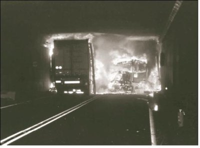
Major tunnel incidents since 1995 have killed 713 people worldwide. From 1999 to 2001, several tunnel fires with multiple deaths occurred in Europe: 39 people died in the fire in the Mont Blanc Tunnel between France and Italy in March 1999, 12 people died in the fire in the Tauern Tunnel in Austria in May 1999, and 11 people died in the fire in the Gotthard Tunnel in Switzerland in October 2001 in which the temperature reached 1,000 degrees Celsius (°C) (1,832 degrees Fahrenheit (°F)) within a few minutes (see Figure 2). These incidents caused significant concern about tunnel safety, resulting in half a dozen large European projects, including UPTUN (Cost-effective, Sustainable, and Innovative Upgrading Methods for Fire Safety in Existing Tunnels). One project, called SafeT (for " Safety in Tunnels" ), is determining complementary aspects of the various projects and ensuring minimum duplication among the projects.
Figure 2: Gotthard Tunnel fire in October 2001. (SINTEF)
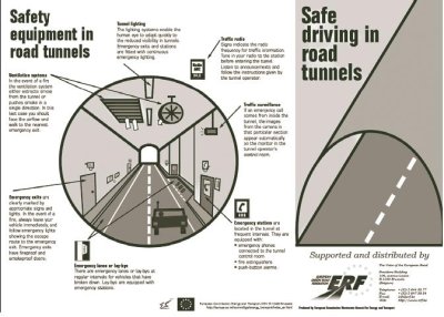
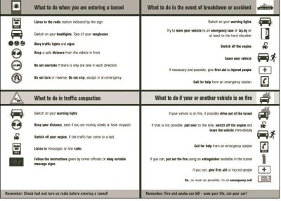
Fire in tunnels continues to be a major area of concern worldwide. Figure 3 (see next page) shows a portion of a pamphlet that gives general details on how to respond if a motorist encounters a fire in a tunnel. This pamphlet has become an official European Union (EU) document and is based on text by PIARC, the World Road Association (see http://www.piarc.org.). PIARC is a nonprofit, nonpolitical association, previously known as the Permanent International Association of Roadways Congress. It has a number of technical committees and focuses on the exchange of knowledge on roads and road transport policy and practices within an integrated sustainable transport context.
Other safety concerns that continue to be investigated for solutions include dew and ice on windshields at portals that cause braking and rear-end crashes and lack of respect for stop lights at tunnel portals. The EU has a common incident reporting format for data collection.
Figure 3: EU pamphlet for motorists in tunnels.
According to the Norwegian Tunneling Society (www.tunnel.no), Norway has 881 road tunnels with a total length of 843 km (524 mi) and 700 railway tunnels with a total length of 316 km (196 mi). All are in rock. The majority of Norwegian road tunnels have one tunnel tube with two-way traffic.
The mountains and fjords of western Norway make tunneling a logical solution for routing motorways across this rugged terrain. The scan team learned that even with the recent tunnel fires in Europe, Norway continues to build tunnels because motorists welcome them because of their better driving conditions and increased safety compared to the alternatives of ferries, roads exposed to avalanches, roads closed during winter, longer driving distances, and driving in bad weather. However, a recent Gallup poll by an insurance company found that 500,000 Norwegians hesitate to use tunnels and 30,000 Norwegians never drive through tunnels. The reasons cited include darkness, narrowness, perception of limited vertical clearance, steepness, length, monotonous driving, fear of being underwater, and poor markings. Of those driving in the tunnels, 15 percent find it unpleasant and 60 percent do not know how to react to a tunnel fire incident
From this poll it is apparent that the main challenges in Norway related to tunnels are to reduce the risk of critical events, construct tunnels to limit fear and worry, develop preparedness plans to minimize the consequences when incidents occur, and inform motorists in advance to increase the possibility of appropriate behavior. The decisions and behavior of the motorists themselves are of vital importance in a tunnel fire incident. More specific information needs to be communicated to motorists because a better understanding among motorists will ensure more appropriate behavior.
The traffic crash rate in Norwegian tunnels is 0.13 incidents per million vehicle-kilometers, compared to 0.30 incidents per million vehicle-kilometers outside tunnels. The entrance-exit zones (portal areas) are the least safe areas of the tunnel. Norway has well-developed tunnel design specifications, and tunnels over 500 m (1,640 ft) long require a specific response plan for tunnel incidents.
For more information, see the Project Delivery section for discussion on the new E39 highway in Norway.
The Foundation for Scientific and Industrial Research at the Norwegian Institute of Technology (SINTEF), founded in 1940, is a nonprofit multidisciplinary research foundation with offices in Trondheim (headquarters) and Oslo. SINTEF has 1,810 employees and is the fourth-largest independent research institute in Europe. It has considerable experience and expertise in traffic management, traffic safety analysis, survey techniques, and human factors, and has a strong affiliation with the University of Oslo and the Norwegian University of Science and Technology. Public and private research contracts generate more than 90 percent of SINTEF's revenues. It has several departments working in the transportation area, including Transport Safety and Informatics, the scan team's host in Trondheim. SINTEF is an active member of the research teams for UPTUN in the human response area and L-surF (feasibility study for a Large-Scale Underground Research Facility on Safety and Security).
Activities include collecting various data for use in evaluating legislation, actual field performance data, and effects of design on motorist behavior. Safety in transport is related to the road user, who may be exposed as a pedestrian, bicyclist, or driver, all subjects of SINTEF's research to find a link between the road user and safety. Most SINTEF reports are public, and some are on the Internet. These reports are typically in Norwegian, although some have a short summary in English.
SINTEF has done extensive work in tunnel traffic management. Its research includes the adjacent network, since an incident in a tunnel has an impact outside the tunnel. Traffic management systems are used to monitor and control traffic in a tunnel and to manage the response to incidents. Researchers clarify and specify the different traffic constraints that should be used for planning and operating the system. They also enable different management schemes for different conditions, and enable a categorization of scenarios as the basis for automatic incident detection. The number of scenarios considered for use in traffic management systems needs to be a minimum to ensure manageability of gathering necessary data and developing responses. SINTEF researchers believe that automatic control of tunnel equipment should be used only for no-disturbance or periodic-disturbance scenarios; all other cases need human intervention using detailed response plans. Parallel and backup systems are required that will operate in various conditions, including smoke, high heat, and moisture. Response plans need to be made uncomplicated for the user in an emergency since drivers will act differently than expected. Because people panic in a fire, input from experts in human behavior is also needed.
SINTEF recommends that a variety of specialties be used in the process of designing a tunnel. Multidisciplinary teams are essential for good, safe designs. Fire brigades and the directorate of public roads both have input and different philosophies. Fire brigades want failsafe systems resulting in zero risk, while the directorate, because of economic restraints, believes that the design must be based on an acceptable level of risk. The contingency plan for each tunnel is linked with the traffic management system.
SINTEF makes use of driving simulators to help determine driver reaction in various situations, including driving through tunnels. In addition, traffic simulation tools are useful in modeling traffic responses to various situations. Models of scenarios can be developed to show traffic reactions to different designs and to verify traffic scenarios.
For more information, see the Planning and Design section for discussion on the use of LED lights in theGrilstad Tunnel and the Incident Management section.
The Norwegian Fire Research Laboratory (SINTEF NBL) is an international leader in full-scale fire tests. In operation since 1934, it is the only fire research laboratory in Norway that does small to large and full-scale fire tests (see http://nbl.sintef.no/). Its focus is on fire safety testing. It has a large fire testing hall measuring 36 m (118 ft) long by 18 m (59 ft) wide by 28 m (92 ft) high for testing large objects. This testing hall can withstand the heat and smoke load of a 12-m2 (129-ft2) gasoline fire and 18-m (59-ft) high flames. The walls are specially designed for a continuous temperature load of 700 °C (1,292 °F).
The fire laboratory conducts tests on the fire resistance properties of various commercial products. These include materials such as surface coating and linings and building components such as wood and plastic pallets. Researchers perform fire suppression testing and have applied it on all types of objects, including buildings, boats, and planes. They have experimented with fires up to 40 megawatts (MW) in size with a temperature of up to 1,400 °C (2,552 °F). Most testing is done according to standards developed under the European Building Directive, which focuses on providing uniform performance standards, specifications, and test procedures for application across Europe.
Some Norwegian tunnels have been built with a polyurethane layer on the face of the concrete tunnel lining to minimize the accumulation of frost. Testing at SINTEF has shown that the insulation can be a fire hazard, so the insulation is being covered with shotcrete in some tunnels to mitigate this hazard.
For more information, see the Planning and Design section for discussion of SINTEF NBL work on fire suppression and experiments using an air curtain to control smoke.
While in Norway, the scan team met with Evert Worm, head of the Center for Tunnel Safety. The center is part of the Tunneling Department in the Dutch Ministry of Transport, Public Works, and Water Management. Worm is also the chair of PIARC C3.3 Working Group 3 on Human Factors for Tunnel Safety.
The Netherlands Organization for Applied Scientific Research (TNO) is an independent research and development organization with 5,000 staff members and 14 institutes in various specialties that do contract research for industry and government, including the Dutch Ministry. TNO is a member of UPTUN and L-surF, and was a project leader for the September 2003 fire tests in the Runehamar Tunnel in Norway in collaboration with UPTUN partners SP and SINTEF NBL.
For more information, see the Planning and Design section for discussion of the Dutch Integrated Safety Philosophy expected to become law in 2006 and the integrated safety plan for the Westerschelde Tunnel. See also the discussion on Dutch escape route signs, LED lights, design fire size, and fire suppression systems.
In 1990, Denmark embarked on an ambitious plan to improve Copenhagen's economy and make the region a center for European transportation. To accomplish this, it is taking the following steps:
These projects were financed by bonds, and it is expected that an increase in adjacent property values will pay for the infrastructure improvements. The payoff period was assumed to be 40 years. Construction loans for the Metro are repaid by income from the Oresund fixed link and the Metro, land sales, land taxes, and a small amount from partners.
The Copenhagen Metro concept originated in 1990. The transit project, a government-owned operation, aims to lower the traffic volume in urban areas, allowing more pedestrian uses. Aesthetics was a significant consideration for the project to help promote higher land values and tax base. The vision of the system was that it would be fast, reliable, safe, and clean.
A fully automatic system (driverless) vehicle was selected. Metro personnel assist users, collect fees, and provide a sense of safety. Separate tunnels are constructed for bidirectional traffic and escape doors are provided every 600 m (1,970 ft).
The project has two contracts for each of the three phases: one contract for the civil work and one for the stations. The stations were built first, and the tunnels were then constructed to connect the stations. The contract was design-build with operation for 5 years, plus maintenance for the civil work. The project started in October 2002 and is scheduled to be completed October 2007.
Tunnels were standard bored 4.9-m (16-ft) diameter bore tunnels with 70-centimeter (28-inch) walkways with handrails. Station placement was determined largely by surrounding development. Station construction was done top down to minimize community impact. The construction sequence was top slab, walls, excavation, and cast bottom slab. All but two stations are about 20 m (65 ft) below street level. Almost the entire length of the tunnels was bored through the limestone layer that underlies the city, minimizing the impact of this work on the community. Hands-on inspections are typical, with service vehicles and inspection platforms provided. In addition, standard details are available for typical repairs such as spalls and cracks. Standard inspection manuals are provided that also specify required inspector qualifications.
Consideration will be made in future work to provide more inspection access, as some details now require demolition to access. More attention will also be paid to water intrusion. Future contracts will also better define quality assurance responsibilities for inspectors. Watertightness of stations will be an item of larger focus.
Two train lines are now operational. The time interval between trains is 200 seconds, with a train in the station every 100 seconds during rush hour. Operations standards are governed by incentivedisincentive, with 98 percent reliability as the standard for satisfactory performance.
The Copenhagen Metro is open and proactive with the media. Its communications department is the biggest group in the company.
For more information, see the Planning and Design section and the Incident Management section.
Rambøll Denmark is part of the Rambøll Group, a consulting group with more than 4,000 employees at more than 70 offices covering the Nordic region and 50 additional locations outside the region. Rambøll Denmark provides technical consulting services in various fields, including infrastructure, transport, and traffic. Its services include operation and maintenance systems and risk management for tunnels.
For more information, see the Planning and Design section and the Maintenance and Safety Inspection section.
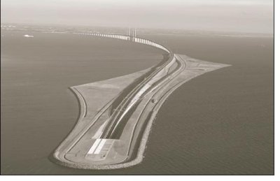
Oresundsbro Konsortiet is a company jointly owned by the Danish and Swedish governments. It owns and operates the Oresund Fixed Link, the 16-km (10-mi) coast-to-coast highway and passenger and freight rail link connecting Copenhagen, Denmark, and Malmo, Sweden. The link, which includes an 8-km (5-mi) long bridge and 4-km (2.5-mi) long tunnel, opened in 2000 and is jointly owned by the Danish and Swedish governments (see figure 4). Rail traffic is operated by the rail authority and is monitored by the train stations in Malmo and Copenhagen. Oresundsbro Konsortiet operates and maintains the nonrail portion. The link is critical to the Oresundsbro Konsortiet vision to see the Oresund Region emerge as a new European powerhouse in cultural as well as economic terms.
The tunnel portion of the Oresund link is located on the Copenhagen end. Because of concerns that a bridge close to Copenhagen's Kastrup Airport might present an obstacle to air traffic, the decision was made to construct a tunnel at the east end of the link. The immersed tunnel consists of two rail tubes, two two-lane road tubes, and a service/escape corridor. A 4-km (2.5-mi) long artificial island was built from dredging the channel and has an entrance to the tunnel. The tunnels typically carry 12,000 to 21,000 vehicles per day. A speed of 110 kilometers per hour (km/h) (68 miles per hour (mi/h)) in the open is normal, including in urban areas. The speed limit is restricted to 90 km/h (56 mi/h) in the tunnels. By law, no bicycles or pedestrians are allowed in the tunnels.
Figure 4: Oresund fixed link between Copenhagen, Denmark, and Malmo, Sweden. (Oresundsbro Konsortiet)
Oresundsbro Konsortiet does not have its own fire brigade or police; it depends on the local authorities for these services. Police patrol the entire link. Joint Swedish-Danish teams patrol two days a week, while on other days teams from one country or the other patrol.
The police have control authority over dangerous goods on the railway. Explosives are allowed through the tunnel if under 1 ton. The Economic Council of Europe is developing new categories for hazardous loads through tunnels that are scheduled to become effective July 1, 2007. If site personnel see dangerous goods markings, they will attempt to make the vehicle turn around, and will report it to the police if they fail.
Many safety considerations were included in the formal risk analysis for the tunnel design. Eight years before commissioning the link, an advisory group was formed to provide advice on safety issues and how to build and operate the link. The advisory group included the fire brigade. Oresundsbro Konsortiet has its own safety pamphlet.
In response to the Madrid and London incidents, Oresundsbro Konsortiet plans to examine its entire procedures for security (e.g., the card access system, locations where terrorists could place explosives, and how to apply elevated alert levels). Danish authorities are assisting with this effort.
For more information, see the Incident Management section and the Maintenance and Safety Inspection section.
The Citytunnel (Citytunnelln) Railway is a Swedish National Rail Administration project that includes 17 km (10.5 mi) of electrified two-track railway and provides the Swedish link to the Oresund Fixed Link. The Citytunnel will connect the Malmo area of Sweden with the train that crosses the Oresund Link from Copenhagen. (The entire Oresund region has about 3.5 million people. Twothirds are on the Danish side and one-third in Sweden.) This passenger rail project includes both commuter rail and intercity rail service and is anticipated to impact the entire Oresund region. The trains are electric only, no diesel. The tunnel geometry is designed for 200 km/h (120 mi/h). The slowest section has a design speed of 80 km/h (50 mi/h), increasing to 160 km/h (100 mi/h).
The total project cost is SEK9.45 billion (US$1.19 billion) in 2001 value. Originally the city of Malmo, the third-largest city in Sweden with a population of 270,000, funded SEK1 billion (US$125 million). The Skane region and the Swedish Railway Authority were the other two original funding sources, while EU made a small contribution. These funding sources were later rolled into the Swedish National Rail Administration. Construction of Citytunnel will take 6 years. Construction started in March 2005 and is scheduled to end in 2011. In addition to the railway, three new stations will be constructed: a below-ground extension of the existing Malmo Central Station, the below-ground Triangeln Station, and the above-ground Hyllie Station. When completed, Malmo Central Station tubes will carry 34,000 travelers per day, Triangeln Station will serve about 37,000 riders per day, and Hyllie Station will serve about 16,000 riders per day.
Citytunnel encountered community resistance to the project because of concerns about potential damage to existing infrastructure caused by the new facilities. Because of these concerns, Citytunnel added an extensive exhibition center for community outreach to educate the public on the reason for and the scope of the project. The project will increase competitiveness of the area, renew vitality, ease traffic congestion, reduce pollution by reducing cars on the road, and provide a safe, efficient, environmentally friendly, and sustainable transportation system.
For more information, see the Planning and Design section and the Incident Management section.
The Swedish National Testing and Research Institute (SP) is a wholly government-owned institute that does commercial testing and has a 10 percent taxpayer subsidy. It has 830 employees in Sweden who work in a variety of technical disciplines. The Fire Laboratory has a staff of 50 and conducts research and testing both nationally and internationally (in approximately equal portions). Its tunnel fire research began in 1993 as part of the Eureka tests started in Norway involving a number of organizations. SP projects include UPTUN, FIT (Fire in Tunnels), and L-surF. The scan teams host was a research scientist with SP Fire Technology.
The industry focus for tunnel fire safety is on both technical aspects and emergency response. SP officials believe that more emphasis is needed on driver behavior and vehicle performance to focus on prevention instead of reaction.
SP officials emphasized these findings from their tunnel fire research:
Frequently asked questions are the following:
SP recommends the following action:
A report comparing fire evaluation methods will be available soon at the FIT Web site at www.etnfit.net.
In September 2003, four large-scale fire tests using wood and plastic pallets were conducted in the abandoned Runehamar Tunnel owned by the Norwegian Public Roads Administration on part of a road system destroyed in a landslide. SP led the testing in collaboration with UPTUN partners TNO and SINTEF NBL. Different semi-trailer fire loads were used, and the highest peak heat release rate ever measured in a tunnel fire test was registered at higher than 200 MW. Gas temperatures in the vicinity of the fire registered above 1,350 °C (2,460 °F). The objec- tive was to observe the rate of fire growth and evaluate how the use of fire suppression or ventilation fans would affect the ability of users inside the tunnel to escape.
Observations included the following:
The following conclusions are drawn from these observations:
For more information, see the Planning and Design section for discussion on SP work on design fire size, fire suppression systems, and ventilation systems.
The A86 West project is the missing link that will complete the second beltway around the city of Paris (see Figure 5. ). The existing beltway is called the " Peripherique." The goals of the A86 West project are to complete the second beltway, improve the commute between suburbs, and reduce congestion. The project is expected to reduce surface traffic by 15 percent. No public funds are being used for the project.
Figure 5: A86 West Beltway project. (Cofiroute)
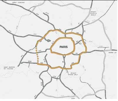
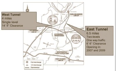
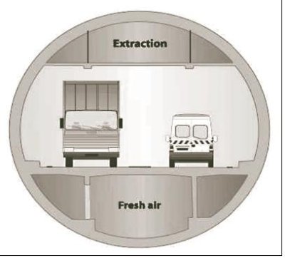
The project was originally proposed in 1988. Major construction began in 1997, but the project was challenged and construction was stopped in 1998. The project encountered opposition from public officials who were concerned about the safety of the tunnel after the Mont Blanc Tunnel fire. It was decided that the project would use new French tunnel safety regulations developed after the Mont Blanc fire (e.g., the tunnels will include twice the number of refuge rooms). Construction began again in 2000 after officials were satisfied that the tunnels would be safe. The project includes an East Tunnel available to cars only and a West Tunnel (see Figure 6) available to both cars and trucks. The scan team meetings focused on the East Tunnel only.
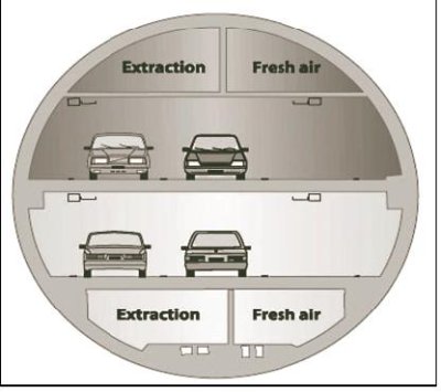
Figure 6: Tunnels on the A86 West Beltway project: West and East tunnels and cross section of tunnels. (Cofiroute)
Cofiroute is the operator and SOCATOP is the design-build contractor for the A86 West project, a € 1.7 billion (US$2 billion) project. Cofiroute, created in 1970, was the first private highway operator in France and now operates 885 km (550 mi) of French highways. It has a contract with the French Highway agency to operate the A86 West project for 70 years. Tolls will vary during the day according to congestion, with high tolls during rush hour.
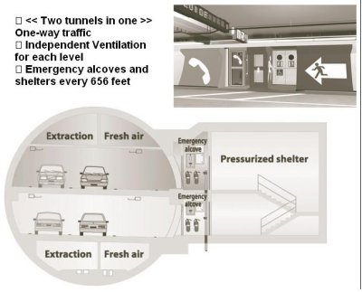
The first phase of the East Tunnel is scheduled to open in 2007 and the second phase in 2009. The tunnel has two levels, one for each direction of travel, and is for passenger cars only. Each level will have two traffic lanes and a breakdown lane. The ceiling height in each level is 2.54 m (8.33 ft) and the clearance is 2 m (6.5 ft). The tunnel is being built using an 11.5-m (37.7-ft) diameter tunnel boring machine (TBM). To protect the environment, a very compact underground interchange with up to three levels of ramps was designed. The project will include tree planting at the ground surface in this area.
The tunnel will have pressurized refuge rooms for up to 50 people every 200 m (656 ft). See Figure 7. Each level of the tunnel will have independent ventilation. The ventilation system is longitudinal during normal operation with extraction capability for smoke management during a fire in the tunnel. Well-marked exits and refuge rooms with bright colors and lights are used to attract the driver's attention in the tunnel. The tunnel will have one emergency access every 800 m (2,620 ft) for firefighters. A water mist sprinkler system is being considered for the tunnel.
Figure 7: A86 West Beltway East Tunnel emergency facilities: cross section of emergency facilities and example of emergency alcove. (Cofiroute)
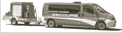
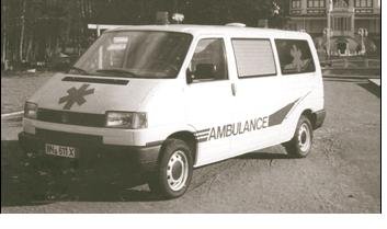
The tunnel will be monitored 24-7 by a staff of 15. More than 400 cameras will be located inside the tunnel and at the access ramps. Cameras will be fitted with automatic incident detection and permanent digital recording. The tunnel will be illuminated with 10.5 candelas per square meter to improve safety. Current French regulations require 6 candelas per square meter. The operator will control the traffic inside the tunnel by detecting incidents, informing drivers what to do during incidents, and activating the emergency response plan. Emergency vehicles with a 2-m (6.5-ft) height have been ordered for fighting fires and assisting motorists inside the tunnels. Three ambulances with a 2-m (6.5-m) height will be parked at the three operation centers. see Figure 8
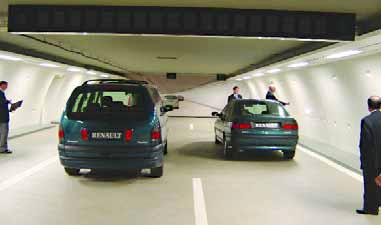
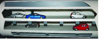
An exhibition center was created to explain the tunnel project to local citizens and public officials, who were initially opposed to the project. The full-size model of one section of the twin roadway tube allows users to experience the tunnel and demonstrates the effectiveness of good lighting and painting. see Figure 9
Citilog is a private company based in Paris that was formed by researchers in 1997 to provide technology solutions for use in tunnels and other transportation operating environments. Its services are being used on the A86 West project.
The A86 West project will use cameras with an automatic detection system that allows the tunnel operator to be proactive. The technology precisely interprets video images, discerns anomalies, and alerts transportation professionals to events occurring in the tunnel. It provides both the most current image of the area of an incident and images of activities that occurred just before the event. The system captures the information the operator needs to make the correct response decision. The images can be used for timely response to emergencies and can provide enhanced security at critical locations. This system can be used to detect a person walking in the tunnel after the train has entered or departed the tunnel. It also can be used to detect a package or object that has fallen from a moving vehicle and smoke inside the tunnel. When the camera detects an object or smoke, the system sounds an alarm to attract the operator's attention.
Concern has been expressed about the impact of cameras on the privacy of drivers. If used to read licenses plates in a crash, the cameras will zoom in to recognize the plates but not the drivers' faces.
The company can perform some system maintenance from a remote location. The system cost is about € 4,230 (US$5,000) per camera for software installation.
In Lyon the scan team met with representatives from the Tunnel Study Centre (CETU) of the French Ministry of Transport, Equipment, Tourism, and Sea. CETU, which is part of the Road General Directorate, has seven departments with 90 staff members. The expertise of the multidisciplinary staff ranges from research engineering to equipment and operations. CETU's basic mission is to develop methodology and regulations for road tunnels based on the complementary functions of research, engineering, and coordination with various professional associations. CETU's efforts include issuing technical reports and recommendations, drafting regulations and standards, applying regulations, checking projects for conformance with regulations, and serving as the Secretariat of the National Commission for Safety in Road Tunnels.
CETU officials offered that they did not have good information on human factors behavior to incorporate in tunnel design or operations emergency response procedures. They said they were undertaking studies in human behavior to integrate into the planning and design process for tunnel safety as well as to develop driver education tools. This includes using sound, visual means, and real-time information transmission via changeable message signs. In the area of driver education, CETU has been asked to evaluate a film prepared for drivers of heavy vehicles.
CETU officials provided an explanation of their approach to tunnel data acquisition, monitoring, control, and communication. The tunnel operator receives information through two linked but separate fiber-optic communication trunk networks. Each trunk network is a dual redundant loop system. One network provides security- related information such as telephone, radio, and video surveillance. The other network is used primarily for maintenance purposes and provides information on electrical, mechanical, and information system status.
For more information, see the sections on Planning and Design, Incident Management, and Maintenance and Safety Inspection.
Figure 8: Special emergency vehicles for the A86 East Tunnel: firefighting vehicle and ambulance. (Cofiroute)
Located on the French-Italian border, Mont Blanc is the highest peak in the Alps at 4,807 m (15,771 ft). Opened in 1965, the Mont Blanc Tunnel brings together two Alpine regions, the Arve Valley in France and the Aosta Valley in Italy. The tunnel is 11.6 km (7.2 mi) long and 8.6 m (28 ft) wide and has over 2 km (6,500 ft) of mountain above it. It averages more than 4,000 vehicle crossings per day.
In March 1999, a fire in the Mont Blanc Tunnel left 39 dead. Immediately after this disaster, a French-Italian steering committee was formed to develop new rules and designs. From 2000 to 2002, the tunnel was redesigned and rebuilt and tunnel management was restructured. Before the fire, the Italian and French companies each managed its own half of the tunnel. Now one company, the European Economic Interest Group (EEIG-TMB), manages the entire tunnel, combining both French and Italian interests with one control room and one incident commander.
EEIG-TMB has 180 employees, half French and half Italian. It has three members on its board of directors: one from France, one from Italy, and a general manager who changes every 30 months. The general manager was initially from France and is now from Italy.
EEIG-TMB has four departments with 40 to 50 employees in each: administration, toll and customer relations, safety (in charge of safety and traffic management inside and outside the tunnel), and maintenance (in charge of routine maintenance and new projects and investments). EEIG-TMB emergency response procedures were used to develop the French regulations.
The EEIG-TMB safety department is in charge of the control room, safety team, and traffic management with real-time information system. Shifts work 24 hours a day, 7 days a week, and each shift has 14 employees, including 10 firefighters. The tunnel has three fire stations: one at each portal and one in the middle. Maintenance systems are tested every day, and a fire test is conducted weekly.
Full-scale safety exercises are conducted every 3 months in conjunction with CETU. For this exercise, the tunnel closes Monday at 7:30 p.m. and opens Tuesday at 6 a.m. The public is notified of the closing dates in the newspaper and on the Internet. The exercise consists of two parts, one for training and one for routine maintenance. The training, which is videotaped, is done to improve organization and cooperation among the rescue services, including firefighters, paramedics, and police from both countries. This training improves cooperation since the two countries have different procedures and may uncover problems with the systems and the response organization. A typical exercise includes 100 emergency response personnel, 40 vehicles, and 30 people with simulated injuries. Participants do not know the specifics of the simulated incident beforehand. A yearly fire exercise is conducted in collaboration with CETU.
For more information, see the Planning and Design section for discussion on escape routes, LED lights, and ventilation systems. See also the Incident Management section.
Joining the meetings with CETU in Lyon was Dr. Alfred Haack of the German Research Association for Underground Transportation Facilities (STUVA), the research arm of the German government. STUVA is a nonprofit, private organization with 225 corporate members, including contractors, suppliers, consultants, academia, and railway and metro operators. STUVA has two departments, one for operations and one for structural issues. Operations department activities include managing ventilation, accommodating disabled passengers, and managing transit operations. Structural department activities include those related to design, construction, and quality assurance. STUVA has also become involved with many international working groups and professional associations, including the International Tunneling Association, German Tunneling Association, and UPTUN. It is involved in several projects, including SafeTunnel, L-surF, and the European Safety Tunnel.
Haack offered that the question of how humans react in emergency situations is a significant issue and that we do not have definitive information to use in tunnel design and operations for emergency incidents. All agreed that human factors behavior is important for tunnel design and operation and that much more information is needed in this area.
Haack suggested that further work should be done to improve the fire resistance of heavy vehicles (trucks). He noted the lack of progress in this area for trucks compared to the European Norms (Standards) and German standards for the construction of rail rolling stock. Material composition and fire rating are included in these rail standards.
For more information, see the Planning and Design section and the Incident Management section.
Figure 9: German end-of-queue warning vehiclesModel of A86 twin roadway tube: full-size model of one section and scale model of twin tube.
In Berne, the scan team was hosted by representatives of the Swiss Federal Roads Authority (FEDRO), the Swiss equivalent of FHWA. FEDRO is responsible for administration of the highway program in the country. FEDRO developed the Switzerland tunnel ventilation directive published in 2004.
In Mitholz, the scan team was hosted by representatives of BLS AlpTransit AG, the main contractor for the Loetschberg Base Tunnel construction, and by representatives of Schneller Ritz & Partner, the design firm for the project. Schneller Ritz & Partner was instrumental in developing the 2004 Swiss Standards Association (SIA) design codes for road and railway tunnels.
For more information, see the Planning and Design section for discussion on the Swiss design codes.
The Gotthard Road Tunnel is part of the A2 Motorway in the Swiss Alps, which serves heavy goods traffic between Germany and Italy. It eliminates 30 km (18 mi) of a twisting mountain pass that is closed up to 6 months of the year because of weather conditions. The tunnel, 16.9 km (10.5 mi) long, is one of the longest road tunnels in the world. Construction began in 1969 and the tunnel was opened in 1980. It quickly attracted 6.8 million vehicles per year. For more information, visit www.gotthard-strassentunnel.ch. Information is also in English.
Several fires in the Gotthard Tunnel have resulted in people staying in cars and dying in as little as 10 minutes, tunnel roof collapse, flashover from vehicle to vehicle, and confusion in getting to refuge rooms. These incidents show the importance of self-rescue.
For more information, see the Planning and Design section and the Incident Management section.
In 1998 the Swiss voted to modernize their rail system and shift transalpine transit traffic from road to railway. Funding was allocated to build the Loetschberg base tunnel, a rail tunnel intended for all types of trains, including high-speed passenger trains with speeds up to 250 km/h (155 mi/h) and transport of all types of goods and materials. The tunnel will extend from Frutigen in the Kander Valley to Raron in the Rhone Valley in the southwestern part of Switzerland. The tunnel length will be 34.6 km (21.5 mi), with a total length of all rail, service, and connecting tunnels of 88 km (54.7 mi). The tunnel will have a capacity for 110 passenger and freight trains per day.
When complete, the tunnel will have dual tubes for its entire length to maintain efficient two-way traffic flow. However, when it first opens in 2007 after the completion of Phase 1, the tunnel will have only one tube for a portion of its length. Traffic will have to be reversed in this portion as necessary to enable the single tube to accommodate bidirectional traffic.
Passenger trains using the tunnel are specially made and have pressure control in the cars to maintain passenger comfort. The trains will run on electricity power by two separate systems. One will operate at 16.7 Hertz (Hz) and feed power to the train itself. The other system will operate at 50 Hz to feed power to all tunnel systems except the train. Each power system will have two supply sources so that power can be supplied from either the north end of the tunnel or the south end. This redundancy will enable shutdown for maintenance or switching in case of malfunction of one supply. The control center for the tunnel is located 10 km (6.2 mi) away from the north end of Thun.
The tunnel drainage system incorporates sedimentation or cooling ponds to ensure that water draining from the tunnel system does not have adverse environmental effects on the Rhone River.
Requirements for construction safety and security are given high importance. The Swiss National Insurance Company insures workers against injury. General requirements provide guidance to the contractor for developing a comprehensive safety program to safeguard workers. The employer has the primary responsibility to take all necessary measures and establish worksite rules to protect employees, and employees are obliged to follow the employer's rules. Construction safety features include the following:
For more information, see the Planning and Design section and the Incident Management section.
Austria has almost 100 road tunnels longer than 1,000 m (3,280 ft) and half a dozen of the world's longest railway tunnels ranging to over 12.5 km (7.7 mi). When the average number of daily vehicles per lane crossing an Austrian tunnel is greater than 10,000, a separate tube is constructed, as defined in the European Directive on Minimum Requirements for Safety in Road Tunnels (2004/54/EG).
Joining the scan team meetings in Berne, Switzerland, to discuss ventilation issues was a professor-researcher from the University of Graz in Austria. The scan team learned of a recent incident in an Austrian road tunnel in which a fire on a tanker truck in the tunnel demonstrated the unpredictability of human behavior as well as the rapid growth of a vehicle fire. In this instance, even trained police officers did not show familiarity with the tunnel fire safety equipment. Shortly after the incident was identified, the operations center stopped traffic entering the tunnel and opened cross tunnels to evacuate those already inside. The driver tried ineffectively to extinguish the fire using extinguishers from his vehicle and from the pullout area. Police responded but did not attempt to extinguish the fire. Tunnel maintenance staff eventually extinguished the fire with the available tunnel fire hoses. The fire brigade response time was 26 minutes.
For more information, see the Planning and Design section for discussion on design fire size, fire suppression systems, and ventilation systems.
The Plabutsch Tunnel is Austria's second-longest road tunnel. It is located in the southeastern region of Austria, in the province of Styria next to the region's capital, Graz. The tunnel is one of several major tunnels along the A9-Pyhrnautobahn motorway, which links central and southeastern Europe. The 10-km (6.2-mi) long tunnel opened in 1987 as a single-bore tunnel with bidirectional traffic. In 2004 a second bore was opened and the first bore was refurbished. Safety features used in the tunnel include fireproofing for all energy supply cables inside the traffic room and traffic monitoring by closedcircuit television (CCTV) with tunnel information displayed in fully graphical mode.
For more information, see the Planning and Design section.
The scan team met with representatives working on two major European tunnel research projects, UPTUN and L-surF. These projects are described below.
UPTUN (2001-2006) is the acronym for Cost-effective, Sustainable and Innovative Upgrading Methods for Fire Safety in Existing Tunnels, a large European project funded by the European Commission to find cost-effective means to upgrade tunnel safety. The project involves 42 EU partners and has a budget of US$19.3 million. UPTUN partners include scan team hosts SINTEF, SP, CETU, and STUVA.
The two main outputs of UPTUN are 1) development of innovative, cost-effective technologies and assessment of existing technologies for tunnel applications, with a focus on technologies in the areas of detection and monitoring, mitigation measures, influencing human response, and protection against structural damage; and 2) development, demonstration, and promotion of a risk-based evaluating and upgrading model for safety level evaluation, decision support models, and knowledge transfer. The spinoff desired from this work is the restoration of faith in tunnels as safe parts of the transportation system, the leveling of trade barriers imposed by supposedly unsafe tunnels, and an increased awareness by stakeholders of the necessity to develop initiatives to link all relevant research.
UPTUN has seven work packages (WP):
WP 1 (prevention, detection, and monitoring) has five products. The database of European tunnels produced in WP 1 is ready. Since it is difficult to describe incidents uniformly, one must be careful using the data. It has technical systems and recent incidents. Reports are scheduled to be published in September 2006. The second and third products-incident analysis and recommendations for prevention solutions, and detection and monitoring systems- are completed. The last two products-new technology and improvements in existing techniques and tests on new technologies and reports-are scheduled to be ready in a few months.
WP 2 (fire development and mitigation measures) also has five products. The design fire scenarios and the acceptance criteria for engineering are ready and are scheduled to be available next year. The efficiency of current fire mitigation equipment, the models describing major influences of mitigating measures on design scenarios, and the guide for engineering cost-effective mitigation systems are scheduled to be ready in 2006.
WP 3 (human response) has four products. Current knowledge and measures, the role of human response in tunnel incidents, and methodologies and systems for handling critical situations are ready. Crisis management of rescue teams is the only work not yet completed. Some EU projects have U.S. participation, but this one does not. The United States, Japan, China, South America, and Australia have exchange through PIARC.
WP 4 (fire effects and tunnel performance: system structural response) has six products. The critical evaluation of burnt tunnel structural data, damage investigation methods, and structural fire test data are ready. The evaluation of spalling risk, repair and recovery procedures, and safety level definition are ongoing work.
WP 5 (evaluation of safety levels and upgrading of existing tunnels) will combine the outputs of other work packages to get a procedure for formulating a new level and describe how to achieve it. Other countries are also bringing in their views; it will be a mix. The five products are a comprehensive inventory of tunnel safety features, criteria to evaluate tunnel safety levels, a procedure for the holistic evaluation and upgrading of safety levels, upgrading recommendations, and the financial and socioeconomic impact of upgrading the tunnels. This work is ongoing.
WP 6 (fire effects and tunnel performance: system response) has four products: full-scale tests, test data on tunnel performance, a validation report on the theoretical model of WP5, and recommendations on upgrading of existing tunnels. The full-scale tests took place in February 2005 in Italy.
WP 7 (promotion, dissemination, education/training, and socioeconomic impact) has six products: a report on economic impact; cooperation with running and future (extra) European projects; a European Tunnel Safety Board; criteria for informing (non) governmental bodies, institutions, and tunnel owners; layout for training and education programs; and promotion material. Some reports are ready; two will follow. One interesting development is that discussions are ongoing to develop European safety laws.
All deliverables are scheduled to be available in September 2006.
The L-surF group (feasibility study for a Large-Scale Underground Research Facility on Safety and Security) is a new 3-year (2005-2007) initiative that will be Europe's future core of tunnel research and development. The objective is to build a strong new European organization dealing with tunnel testing, research, training, and development of different products. It is a major EU-supported activity focused on safety and security in underground infrastructures within the Sixth Framework Programme of research funding. It has a budget of 3.3 million (US$3.9 million), with the goal of harmonizing safety and security in Europe, bringing research and development to the forefront with large full-scale tests, and providing a means to promote tunnel research on safety and security internationally. After 3 years, the plan is to have a set of drawings that show how a center with all tunnel research in Europe will look.
The L-surF design study includes work packages with different partners responsible for different tasks, such as the following:
Core member organizations for this initiative are the following:
The EU has agreements governing road signage, including signage standards for tunnels, through an affiliated group, the European Commission. As a result of the Mont Blanc and Tauern tunnel fires, the commission launched two initiatives. The first initiative was research projects for road tunnel safety. The second was legislation via a 2004 directive that applies to tunnels longer than 5 km (3 mi) on the trans-European road network.
The directive provides the following:
The Dutch integrated approach for tunnel design is being used as a guideline in the Netherlands and can be accessed at www.tunnelsafety.nl. Developed in 2001, the guideline will be part of a law scheduled to be discussed in the fall 2005 in the Dutch Parliament and to become effective in 2006 if passed.
In the late 1970s the Netherlands shifted from practical tunnel design to a probabilistic design approach. This approach is largely a result of lessons learned when much of Holland was flooded in 1953. The approach determines the risk in a tunnel based on a quantitative risk analysis that considers probability and likely consequences of a particular type of incident, given a set of predictable safety measures. This work formed the basis for Holland's tunnel design standards.
In the mid-1990s, the probabilistic design approach was questioned. While it gave a level of expected safety, it did not address what happens or should happen when a disaster actually occurs. The scenario analysis, a deterministic approach, considers tunnel emergencies in the design phase. For this method the emergency response plan, incident scenarios, and safety design features are defined and then evaluated. The probabilistic approach and scenario analysis resulted in similar designs.
Several serious tunnel incidents across Europe in the late 1990s to early 2000s and increasing surface land development resulted in pressure to develop a framework in which all safety issues could be described. This integrated safety philosophy provides a structure to solve problems and allows the objective comparison of alternate tunnel designs. It is " integrated" because it was developed in cooperation with all relevant parties. It covers both the construction phase and the operating phase, and it addresses all safety aspects in the tunnel and its immediate environment. It distinguishes between proactive, preventive, preparatory, repressive, and followup measures, and the tasks and responsibilities of all those involved are clearly defined.
Several terms are used in the probabilistic approach to the safety issue, where a large number of incident scenarios are analyzed for probability and associated consequences. The Dutch use the term " risk" to dissociate safety from its emotional association, and differentiate between " external" safety and " internal" safety. External safety is related to the risks of individuals or groups of individuals in the vicinity of a source of danger such as a highway crash. An extra risk is created when the road is underground, producing extra dangers internally. An example is a tunnel fire where motorists are exposed to heat, smoke, toxic fumes, and possibly explosions from which they cannot easily escape. This is referred to as internal safety.
In addition to the probabilistic approach, a limited number of scenarios can be systematically analyzed in more detail. In this case, actual incidents and associated rescue options are examined. The scenario analysis in this deterministic approach includes the concept of self-rescue, in which emergency services have not yet arrived and individuals must rely on themselves to survive the emergency. Of course, other emergency response measures aside from self-rescue are also considered.
A third approach is the ALARA principle. ALARA stands for " As Low As Reasonably Achievable." In this approach, the designer uses common sense to determine where extra safety benefits can be achieved in a practical way at minimum cost.
Project safety can be evaluated using the Safety Chain. The basic structure of this chain is as follows:
With the safety philosophy, intervention should occur as high up in this chain as possible to prevent the incident. This philosophy can be used on all types of tunnels, although the details will vary depending on the individual type. An example of its use is the integrated safety plan developed for the Westerschelde Tunnel.
The Westerschelde Tunnel is a 6.62-km (4.11-mi) twin-bore tunnel 60 m (200 ft) maximum below sea level with two lanes each and 12-m (39-ft) cross tunnels every 250 m (820 ft). It crosses the Westerschelde River to connect the southern part of the Zeeland Province to the rest of the Netherlands; the only connection previously was provided by two ferries. Safety measures cost € 160 million (US$190 million), or 30 percent of the total € 550 million (US$650 million) construction cost.
This project was the first use of an integrated safety plan for a large project. It was jointly developed by the Ministry of Transport, Public Works, and Water Management and the Ministry of the Interior. The integrated safety plan took more than 2 years to develop because of the large number of participants.
The integrated safety plan is divided into the following components:
Each component addresses the safety aspects specific to that plan, the overall safety chain, and the tasks and responsibilities of the relevant parties.
The most significant safety measures in the proactive stage were the following:
The most significant safety measures in the preventive stage were the following:
The most significant safety measures in the corrective and repressive stages were the following:
The safe maintenance plan was completed shortly before the opening of the tunnel so that the latest information could be included. It includes descriptions of the various maintenance operations, conditions for safe maintenance, and implementation of the maintenance operations.
TNO believes that this philosophy and the corresponding safety management system guarantee a high level of safety, with the residual risk reduced to an acceptable level.
Special consideration in the overall safety analysis was given to the situation in which an incident forces road users to flee from an affected bore to an unaffected bore. The scenario is as follows:
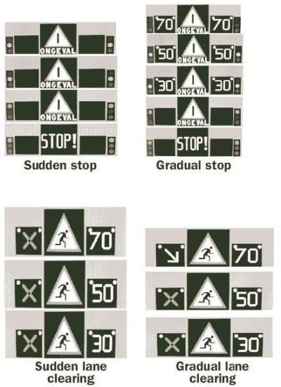
To avoid road user panic, it was decided to unlock the doors in both bores at the same time. This meant that those escaping to the safe bore might reach it when cars are still passing through it. To increase safety, a traffic information system for the unaffected bore was developed, and the following four options (see Figure 10) were considered:
These four approaches were tested in a simulator. The major conclusions from this test were that lane clearing proceeds smoothly but stopping traffic does not, and that the gradual lane clearing approach is most compatible with the signaling used outside the tunnel and most effectively clears the unaffected bore for emergency services. Individuals in the test said that the gradual lane clearing was good because they recognized the arrow from its other uses; this shows that users do not pay attention to red crosses or lights, but do pay attention to established signage. If the evacuation is successful, the situation is considered satisfactory because human life has a higher value than cars and facilities.
Figure 10: Scenarios for evacuation safety in tunnels: sudden stop, gradual stop, sudden lane clearing, and gradual lane clearing. (Dutch Ministry)
The design process and criteria for safety-related features in the Copenhagen Metro are based on European standards and modern European installations. It begins with the concept and proceeds to system definition and application conditions, to risk analysis (which may be repeated at several stages of the life cycle, depending on modification and retrofit), to system requirements, to apportionment of system requirements, to design and implementation. The process further considers manufacture, installation, system validation (including safety acceptance and commissioning), system acceptance, operation and maintenance, performance monitoring and modification/ retrofit, and decommissioning and disposal.
This is the first project of this complexity in Danish railway history, and at the start of the project there was no established set of standards. Subsequently, many standards from a variety of sources were adopted for the project. The main ones are mentioned here. The German code, BOStraB, was used as the overall code and standard framework. Compliance with Danish building regulations, Eurocode EN50126, and NFPA 130 (as a supplement to BOStraB) were required. Vulnerability assessment was done by the consultants as part of the design.
The Metro safety requirements were defined by the employer in agreement with the Ministry of Traffic and encompass quantitative risk acceptance criteria, norm-based requirements, and contributions by emergency services. The Metro risk acceptance criteria must have the same level of safety as other systems in Europe. Statistics from Skytrain, Vancouver, VAL, LuL, DSB S-tog, etc., were used for analysis because they were believed to be similar systems. A hazard identification and analysis document was used to develop design criteria. As risk changes, these assumptions must be revisited occasionally and possible new countermeasures introduced.
The ventilation system was designed to provide redundant airflow paths to provide for the loss of a vent shaft. Ventilation initially works automatically but has a manual override/backup.
Cut-and-cover sections use stainless steel mesh to reinforce and minimize spalling. Strain in the lining and corrosion and lining distortion are all monitored by instrumentation and imbedded sensors. Fire protection is provided by a sacrificial stainless steel-reinforced protective lining inside the tunnel.
The codes take accidental loads into account (e.g., derailment and fires). There are no specific codes for concrete lining damage, flooding, or blast design. The level of blast is chosen by the owner. Sweden limits the amount of explosive goods that can be taken on one train and will not allow dangerous cars during the day (on a case-by-case basis).
The following are some of the safety features in the system:
Emergency drills are planned with emergency services to test and verify response plans. Mutual aid agreements exist for the region for response, but interoperability of communications equipment does not exist.
Rambøll uses risk management as the basic approach to designing railway infrastructure safety systems. The European community establishes standards for a process to perform risk analysis of safety systems. The owner determines the design criteria to be used. Rambøll develops the risk analysis by breaking the project into its components and presenting them in matrix format. It develops a mathematical model of the system and uses the results to provide the client with the information to assess the various options on the basis of cost versus risk. An example of the type of input for the risk analysis is the modeling for a fire on a subway train. Computational fluid dynamics (CFD) was used to evaluate the spread of smoke versus time. All materials used in the train construction were incorporated in this model, but it did not incorporate fire suppression.
Another example is the safety analysis for the design of the Copenhagen Metro in the 1990s. The focus of the analysis was on train-related passenger safety and structural reliability. The analysts did not focus on an explosion in the tunnel in developing the design because they believed explosive forces could not be designed for cost effectively.
Rambøll also did design work on the Oresund Link tunnel. The design was based on European codes rather than specific codes from either Denmark or Sweden, as a way of being neutral. The basic approach was to look at bridge design guidance and adapt appropriate provisions to tunnel design. Specific design requirements were developed as needed where no guidance was available. For fire design, the company developed a project-specific level of risk for different scenarios. This led to the installation of fireproofing liner to protect the concrete from spalling.
Future trends in risk analysis include developing models that incorporate health, safety, environmental factors, and quality into a single model. An increased focus on terrorism is also a future trend, as is the protocol for facility inspection based on risk analysis.
The safety policy for Citytunnel is that it will meet strict requirements on safety for people, properties, and the environment. High accessibility and safety are important aspects for increased use of railway traffic. A high level of safety is achieved by attaching safety to planning, design, and construction and getting continuous feedback from other interested parties.
The four ruling laws that govern the design and construction are the Planning and Building Act, the Swedish Environmental Code, the Railway Construction Act, and the law on technical requirements for buildings and plant structures. Checks are made through risk analyses; meetings with the fire brigade, police, and others to discuss safety problems and solutions; scenario staging; and annual reports to authorities on current and planned safety measures. However, no specific laws or regulations govern underground railroad operations.
The project safety objectives were to conform to the methodology and acceptance criteria contained in BVh685.30. This meant that the tunnel operation was to be as safe as open, at-grade track operation from derailment, collision, fire, etc. The stations were required to be as safe as any other building used for public assembly; building codes are used even though the existing building regulations were not designed to apply to tunnels. The evacuation goal was to have safe evacuation without assistance. The safety concept included an emergency evacuation procedure, a rescue operation procedure, a risk analysis, and safety systems. Highlights for specific criteria that resulted include the following:
Normal ventilation is caused by train movement. The jet fans are used only in an emergency to control smoke and fire. The fans are along the entire system and have pressure relief vents to reduce wind on the platform to an acceptable level. The stations have chimneys to release smoke.
There are also requirements for rescue services and environmental regulations. Many of these building code requirements do not necessarily comport with specific considerations for tunnels. The government is working with the planning and building authority, fire brigade, and others to determine whether special tunnel regulations are needed.
Citytunnel met with the fire brigade and relied on the Eureka tests and the Swedish National Testing and Research Institute (SP) for guidance. From the safety concept, Citytunnel evaluated other work, including fire simulations, evacuation simulations, and crash safety evaluations for tunnels and stations to develop risk analyses. From this it developed Safety in Technical Systems (SITS).
Fire brigade intervention should be possible for certain, but not all, scenarios. The 15-MW fire is the standard because the concern is that the fire brigade would be able to extinguish only relatively small fires. Citytunnel developed a matrix of responsibilities and calculated fire evacuation times. From the analysis of the matrix, it was determined that by the time the fire is at the 50-MW stage, the fire should be left to burn, and the response should emphasize search and rescue.
Fire smoke simulations were done for fires up to 15 MW for the performance-based design. Time-temperature curves and temperature resistance requirements were developed with help from SP. Researchers simulated fires and evaluated various evacuation patterns. The current risk analysis for passengers being evacuated is an acceptance matrix from the rail authority, and Citytunnel is replacing the matrix with a new frequency curve.
This work resulted in identifying many safety systems. To limit disruption and increase safety, Citytunnel installed various equipment (e.g., CCTV) for the full length of the tunnel to allow the control center to determine whether a disruption is required. Discussion is ongoing on the use of CCTV, however, and some do not favor camera use. Staircases are enclosed with fire-resistant glass and designed for over-pressure. The fire brigade has access routes that are separate from the evacuation route.
General requirements are that the evacuation time determines the maximum capacity needed, with 60-minute functionality and 120 minutes for rescue operations. When feasible, emergency systems should be combined with normal operating functions. Automatic operation is recommended since many scenarios are too complicated for manual operations.
CETU officials explained that France had been working on technical standards for new tunnels and the standards existed in draft form in 1999. As a result of the tunnel fires in Mont Blanc and Tauern (Austria) in 1999, the French launched two initiatives. The first was a 3-month joint French-Italian investigation and report on the Mont Blanc Tunnel fire. The second initiative was a safety check of the 40 road tunnels longer than 1 km (3,280 ft), with general recommendations for safety of all tunnels and specific recommendations for each one that could go as far as closing the tunnel completely or closing the tunnel to heavy vehicle traffic.
Also, new regulations were issued in 2000 that included technical aspects covering minimum safety standards, operations (new to tunnel standards), and safety procedures for both new and existing road tunnels. These regulations as well as all subsequent French regulations cover road tunnels longer than 300 m (984 ft).
In addition, a circular provides enforcement power for all government-owned tunnels, requiring owners and operators to get authorization from the local governing authority (prefecture) to operate existing road tunnels. Owners must get advice from the prefecture to operate existing tunnels. The prefecture uses a National Evaluation Committee for technical advice. Determining safe operation is based on a safety analysis of each tunnel consisting of a review of likely scenarios, an evaluation in detail of three or four specific scenarios for safety risk and mitigation measures, and a report to the prefecture on safety. This safety analysis is called " specific hazard investigation" and has been incorporated in the European Directive 2004/54/EC (see below).
A law on safety of transport infrastructures and systems was passed in 2002 and made applicable in 2005 for nongovernmentowned road tunnels. The law made it compulsory to carry out a safety examination every 6 years, have new road tunnels adhere to the standards, and have owners of existing road tunnels set the goal to achieve compliance. This does not imply applying strictly recommended safety measures; different measures are acceptable as long as the same level of safety is achieved.
The French method for tunnel safety risk analysis is basically the aforementioned deterministic specific hazard investigation involving scenarios and mitigations. A different risk analysis method is used to decide whether dangerous goods should be allowed in a tunnel. It uses the Quantitative Risk Assessment (QRA) model jointly developed by the Organization for Economic Cooperation and Development (OECD) and the World Road Association (PIARC), and sold by the latter. As a first step, the average number of fatalities per year in the tunnel due to dangerous goods incidents is calculated, supposing all dangerous goods are allowed. If this figure is below 10-3 fatalities per year, dangerous goods are not considered significant in terms of risk, and the decision is based on other criteria. If not, the method employed involves a quantitative analysis to calculate risk for travel routes through the tunnel as well as alternate travel routes. The risks are then compared for the various routes. The first criterion used is the average number of fatalities per year on each route:
Existing road signs banning all or part of dangerous cargoes are used for enforcement. A new European classification is under preparation and should make it possible to differentiate among five groupings of dangerous goods labeled A to E. In a very few tunnels, the toll gate facilities can be used to stop the passage of hazardous and dangerous goods. Regulations can range from allowing all or some categories of dangerous goods to pass through, to pass through under prescribed circumstances, or not to pass through under any circumstance.
Germany had standard regulations for the design of new tunnels, entitled RABT, that had been updated in the 1980s. New standards were published in 2004 after the Mont Blanc and Tauern tunnel fires. The new standards raised the design fire scenario from 15 to 20 MW to 30 MW, with provision for 50 MW for tunnels with a high number of heavy vehicles (e.g., 4,000 per day). The new standards are compulsory for new federal roads and for state and urban road tunnels using federal funds. Germany will spend € 600 million (US$709 million) over 10 years to upgrade tunnels to the new standards.
Switzerland-Swiss tunnel design codes adopted in 2004 are now available in English. The set is produced by the Swiss Standards Association (SIA). The previous edition, SIA 198-Underground Construction (1993), covered regulations on execution, with design mentioned only briefly. The current codes are directed toward design engineers, owners, operators, and those involved in site supervision and execution of construction works.
SIA 197-Design of Tunnels, Basic Principles covers the basic principles to take into consideration in designing traffic tunnels (railways or roads), including the aspects of safety and environmental impact. It also includes the regulations dealing with the design of an underground structure following the SIA structural codes. The special features to consider in the case of road and rail tunnels are covered in the two specialized codes, SIA 197/1-Design of Tunnels, Railway Tunnels and SIA 197/2-Design of Tunnels, Road Tunnels. The three copyrighted documents, published by SIA, and are available by writing PO Box CH-8039, Zurich, Switzerland.
The tunnel designer needs to design the tunnel for the next generation's tunnel managers. Systems should provide for responses that are as simple as possible.
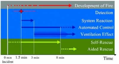
The primary purpose of ventilation is to support self-rescue and aided rescue within 8 minutes (see Figure 11). Influences on the design fire include buoyancy, critical velocity, and smoke production. For tunnels with two tubes, an escape passage should be provided every 300 m (980 ft) between tubes and every third should allow for access by emergency vehicles. For tunnels with a single tube, an escape gallery leading to the open should be provided every 500 m (1,640 ft) at 1 percent roadway grades to every 300 m (980 ft) at 5 percent and greater roadway grades. A parallel safety gallery should be provided for long tunnels. These requirements are now part of the Swiss standards. The new directive sets a standard and defines minimal requirements. The main goal of the tunnel ventilation requirements is the rapid control of the longitudinal flow. Ventilation and escape routes must be coordinated into one concept.
Current standards require an automatic linear temperature detection system (LTDS) video including incident detection. Fundamental requirements are detection of a fire within 1 minute, start of ventilation within 1 minute, and system reaction within 3 minutes. Requirements for smoke detection are to locate hot and cold smoke within 60 seconds and within 100 m (330 ft), or possibly up to 300 m (980 ft), depending on type of traffic, with a very low rate of false alarms. Measurable items include smoke (opacity), CO, video optical detection, linear temperature, and local temperature.
Fire in tunnels always means smoke. Experiences from fires greater than 30 MW, such as in the Gotthard Tunnel, indicate opacity much greater than reported by the LTDS. For the 2004 Baregg Tunnel fire, the LTDS took 7 minutes to detect the fire.
Lighting improvements include 25 percent increased efficiency in portal zones and traffic-dependent adjustment of the illumination level. Temperature resistance of the lamp is 250 °C (480 °F) for over 1 hour. " Awareness rising zones" in special areas of the tunnel provide up to 10 times normal illumination. Emergency niches and awareness rising zones are provided with emergency phones, water supply, and other safety equipment.
New escape route signing to enhance self-rescue was developed for the Dutch Ministry by TNO. The key to enhancing self-rescue is to let motorists know what to do and how to do it, and to emphasize that they need to leave the event area as soon as possible.
Simulation studies have indicated the following:
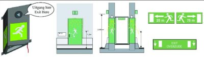
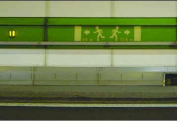
To assist users, TNO did research to make signs that are visible, clear, and logical. Now the Netherlands has a sign standard that consists of a pictogram with a white running figure on a green background. Signs are installed on and near the escape doors. See figure 12. In case of an emergency, LED lighting at the escape doors increases the visibility of the escape route. Pictograms with white lettering on a green background showing the direction and distance to the escape doors are required on walls every 25 m (82 ft). Much discussion occurred on which languages to use for the signs; it was decided to use Dutch and English. Another idea, which has become standard, is to put arrows on the pavement at escape doors. The arrows are raised so they can be felt and laminated for long-term wear.
The standard also includes sound. The Dutch initially used a chirping alarm as an effective audible device. It was audible and locatable, but frightening. In early 2005 TNO developed an enhanced system with the addition of spoken words in Dutch and English to give directions. The revised sound-voice combination to help motorists locate the escape doors is now the standard in the Netherlands.
Figure 11: Ventilation to support self and aided rescue (FEDRO).
As designated elsewhere in Europe, refuge room doors are green with prominent display of white running figures, and similar signs are installed along the tunnel length to show the direction and distance to the refuge rooms (see Figure 13).
Figure 12: Sensory combination for location of escape doors. (Dutch Ministry)
The tunnel has fully automatic escape route signals with selective display of escape direction determined by the emergency.
Several years ago, the Norwegian Public Roads Administration hired SINTEF to study the use of LED lights in the Grilstad Tunnel near Trondheim. The tunnel, 700 m (2,300 ft) long, consists of two tubes with two unidirectional lanes per tube and has an average of 10,000 vehicles per day in each direction. Its posted speed is 80 km/h (50 mi/h). It has ordinary roof lighting and LED lights at 20-m (66-ft) spacing at each outside edge of roadway (see figure 14) and 15 m (49 ft) at both ends. The objective of the project was to obtain driver opinions on security, safety, and comfort and to study driver behavior as a result of different light intensities.
A week-long testing program was conducted in which LED-light intensity was varied at different times of the day, but with 100 percent ordinary lighting on the roof. Driver opinions were solicited to determine lighting level and spacing adequacy. The most satisfying LED-light level was found to be 47 percent intensity with 100 percent ordinary roof lighting. The normal 100 percent LED-light level was perceived to have too much glare.
Driving behavior under various lighting levels was also evaluated. Speed was not significantly impacted. The LED lighting, however, did influence the vehicle's lateral position, with optimum position at 100 percent LED lighting. Drivers felt safer and moved closer to the shoulder as the LED intensity increased.
A fire drill was conducted in the tunnel before it was opened, and the fire department found the LED lighting useful for evacuation. LED lights are favored in Norway because in the winter, reflective striping becomes covered with snow spray within 2 weeks while LED lighting remains visible.
Netherlands-In the Netherlands, the use of LED-lighted escape doors has become the standard (see Figure 13) because officials believe this makes escape routes more visible in an emergency. Strobe lighting was tested but is not used because flashing pathway lights can be confused with the lights used on first-responder vehicles.
LED lights were installed along the edge of the tunnel at regular intervals of about 10 m (33 ft) to clearly identify the edge of the roadway. The majority of these lights were a highly visible yellow color. Spaced among the yellow lights at 150-m (490-ft) intervals were blue lights. See figure 15. Motorists are instructed through formal (for truck and bus drivers) and informal driver education to keep a safe distance between them and the vehicle in front, and that distance is indicated by the spacing of the blue lights. This visual cue is more reliable than asking motorists to establish distance between vehicles using speed-based guidelines.
Figure 13: Examples from the Mont Blanc Tunnel: tunnel escape route and tunnel escape route sign.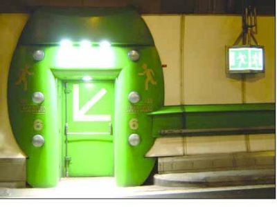
A door inside the Mont blanc tunnel. The door is painted green with yellow arrows and running figures in the direction of the door handle. The green paint continues around the door to make it more visible, then extends in a horizontal wide stripe along the tunnel wall at about waist level.
European countries differ on their design fire size (e.g., Sweden uses 15 MW and Austria and Switzerland use 30 MW). The 2004 German standards raised the design fire scenario from 15 to 20 MW to 30 MW, with provision for 50 MW for tunnels with a high number of heavy vehicles (e.g., 4,000 per day).
For the design fire scenarios in the Netherlands, TNO did tests to develop time-temperature curves for fires that last 2 hours. As a result, the Dutch standard now is for every tunnel in the basic road network to resist a 2-hour fire at 1,350 °C (2,460 °F). TNO found fires as high as 1,400 °C (2,550 °F).
Sweden uses a design fire of 15 MW. SP reports that large fires from semi-trucks and tankers can cause another truck to ignite as far away as 100 m (328 ft). SP research shows that the fire brigade cannot handle large semi-truck or tanker fires, and that for high-megawatt levels, they are considered " fire zones" in which no one can survive.
In Switzerland, a design fire of 30 MW represents a loaded truck. Temperature rise is 65 degrees Kelvin over a distance of 800 m (2,600 ft) within 10 seconds. Influences on the design fire include buoyancy, critical velocity, and smoke production.
A 100-MW design fire is recommended in the annex to NFPA 502. Fires greater than 100 MW have been documented with heavy goods vehicles.
The UPTUN project is putting a large amount of effort into developing methods to achieve fire suppression in tunnels. Fire suppression systems now vary in European countries.
Figure 14: LED lights on roadway edges in the Grilstad Tunnel. (SINTEF)
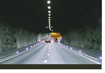
Figure 15: LED lights in the Mont Blanc Tunnel: yellow for edge delineation and blue for vehicle spacing.
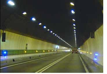
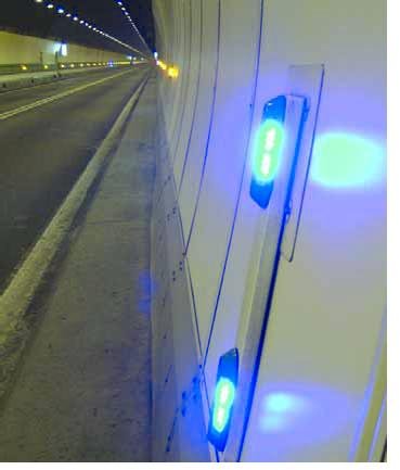
SINTEF NBL has the capacity to create full-size mockups to test fire suppression. Testing of water mist systems has produced good results but requires that the system have the proper design to work properly. Water is good because it absorbs heat well. Full-scale testing is required.
Fixed water-based fire suppression systems for tunnels are found in very few countries. Japan uses sprinkler systems, typically 6 liters per square meter per minute. Water-based fire suppression systems have the following potential advantages:
Water mist fire suppression systems (e.g., 2 liters per square meter per minute) reduce the fires to 30 to 60 percent of their original size but do not put them out; the intent is to keep the smoke and heat down. These fire suppression systems have high installation and maintenance costs.
The Dutch Ministry has a pilot project using a compressed air foam system in the Roertunnel on the A73 motorway in the Netherlands. The tunnel will have this additional safety installation because traffic includes liquid propane gas (LPG) tankers. The Dutch believe that in this typical application (LPG tankers), compressed air foam is better than a sprinkler system, although more expensive.
The September 2003 Runehamar Tunnel fire tests of semi-trailer loads were conducted with a fire size up to 200 MW. SP observed that if users are expected to stay in their vehicles, it is best to use fire suppression. People have a high probability of escape if fire suppression is used to keep the fire below 30 MW. Human behavior studies have shown that people tend to stay in their vehicles much longer than they should.
If suppression systems are installed in high-traffic tunnels, SP recommends that they be simple and robust with an emphasis on both performance and maintenance.
CETU discussed the use of water deluge systems, either the mist or sprinkler type, as a means to contain fire and improve safe evacuation. CETU officials indicated that they are considering this and believe that more study is required.
STUVA provided information on Japanese practice, where water suppression is used for tunnels over 10 km (6 mi) long or over 3 km (2 mi) with high use. However, STUVA noted that there are issues with water suppression. Current practice assumes that well-designed ventilation systems without suppression are best, until further research shows otherwise. Water systems can compromise the stratified smoke layer and in some cases make evacuation more difficult. STUVA indicated that while some advocate mist systems, many are awaiting the results of further research from studies by the UPTUN and L-surF projects.
The purpose of water-based fire suppression systems is to reduce the heat load. It is also easier to breathe moist smoke. Another advantage of using a sprinkler system is that the chance of flashover from one vehicle to another is reduced. Structural damage from a fire is also typically less when a water-based fire suppression system is used.
However, water-based fire suppression systems destroy the smoke layering, and smoke layering can allow users adequate time to evacuate in a fire incident. It is desirable to keep the smoke layering system as long as needed to allow everyone to evacuate. The smoke would need to be reduced by 95 percent to have adequate visibility after the smoke layering is destroyed.
The use of water sprinklers is a big debate in PIARC. Japan and Australia mandated use of sprinkler systems. Europe does not have a regulation that requires a water system. Austria has concerns about the use of sprinklers in tunnels, and currently does not allow them to be used automatically. Austria has two tunnels with sprinkler systems: one in a very short tunnel with manual activation only, and a second one in a 5.4-km (3.4-mi) long tunnel that is in the installation phase. Austrian regulations say that the operator must evaluate the situation. If there is no smoke layering, then a water mist system can be used; if there is layering, the operator must wait to use the water mist system until everyone has evacuated. The decision is based on the air speed and the sprinkler system. The sprinkler must be above the fire to be effective. A water-based fire suppression system is allowed in the first 10 minutes only if everyone has evacuated the tunnel. An Austrian guideline defines the minimum requirement of fire suppression systems and the operation procedures for the ventilation.
Water mist has the advantage that small droplets reduce heat better, but water mist also reduces smoke layering and visibility. An advantage of water mist over sprinklers is that it uses less water. One disadvantage is that the water mist system can freeze (heating has to be provided at the portal regions). A problem in the Alps is that water may not be available in the required amount and it is difficult to bring water to the site, store it, and distribute it. As a result, Austrians have little to no experience with water-based fire suppression systems.
Over the recent past in Europe, interest in fresh air and the environmental impacts of ventilation has decreased, but interest in safety has increased as a result of the many tunnel fires that have occurred.
Currently, ventilation design criteria vary throughout Europe and elsewhere. PIARC is working to develop a harmonized approach to tunnel ventilation. Under PIARC's guidelines (now a working document, but scheduled to be converted into guidelines in 2007), for a tunnel with unidirectional traffic flow, ventilation airspeed is maintained at between 1.5 to 2 meters per second (m/s) (4.9 to 6.5 feet per second (ft/s)) in the same direction as traffic. For bidirectional traffic, air speed is maintained at 1 to 1.5 m/s (3 to 4.9 ft/s) in the same direction of travel except to within 500 m (1,640 ft) of the portal, depending on the evacuation procedure.
In Europe ventilation is controlled in normal mode mainly by opacity (the spacing of the optical sensors varies). In incident mode, various detection systems are used. Heat detection (either by linear heat sensors or laser systems) provides the main information. Some countries include opacity, with optical sensors in very short intervals of 100 to 200 m (328 to 656 ft). CCTV has proven to give very fast detection. Because the rate of wrong signals is still very high, however, this system is used mainly for information (alert) and the operator has to confirm and trigger the fire alarm manually.
SP is experimenting with ventilation systems to control smoke and remove the heat to prevent the fire from spreading.
Sweden does not recommend installing water sprinklers in tunnels. SP speculated that in 10 years Europe may go to transverse ventilation with water spray, rather than longitudinal ventilation, to handle the bigger fires that can result from high congestion. An exhaust vent stack may be a better system than blowing smoke longitudinally throughout the tunnel; a water spray could be used in the duct work to keep it cool.
Passenger rail cars burn at 10 to 35 MW. If the windows break or fall out or if the doors are left open, the fire is ventilated and will burn faster and hotter. To control smoke and prevent the fire from spreading from such occurrences, ventilation from both sides is needed.
The September 2003 Runehamar Tunnel fire tests of semi-trailer loads had fire size up to 200 MW. Researchers observed that if the expectation is that the users will evacuate immediately, the fans should be turned on to full power. The smoke level rises very rapidly, and in 5 minutes the area is completely engulfed, providing very little time to escape (as little as 1 or 2 minutes).
The Mont Blanc Tunnel has semitransverse ventilation, with air pushed into the tunnel. Eight fresh air longitudinal ducts are under the roadway, four on each end to push air. The first duct pushes air the first 1,500 m (4,900 ft), the second air duct pushes air the next 1,500 m (4,900 ft), and this pattern continues to the tunnel center. The 76 jet fans and 20 wind meters in the tunnel provide constant air velocity in the tunnel. An air speed of 8 m/s (26 ft/s) is the maximum velocity permitted at the exit portals. A display shows the air speed inside the tunnel. In normal operations, the air flow curve is a straight line and the point of zero velocity is at the approximate center of the tunnel. If a fire occurs in the tunnel, the operator moves the point of zero velocity to the fire location, and seven dampers at the crown of the tunnel open to extract smoke. Changes in barometric pressure can move the zero-velocity point outside the tunnel entirely. In severe conditions, the zero-velocity point cannot be managed and the tunnel is closed.
The original ventilation was provided by four shafts in the mountain and two at the portals. Fresh air is supplied through an overhead gallery on the left side of the tunnel roof to ducts in the lower part of the tunnel walls. Ducts are on the same side as the refuge rooms, which are located every 250 m (820 ft). Exhaust is provided on the right gallery in the roof. The ventilation design is transverse.
Traffic type (density and volume) will drive the choice of the system (see Fire and Smoke Control in Road Tunnels, PIARC 05-05-B). The basic type is longitudinally ventilated with jet fans, quite common in shorter tunnels. Most new tunnels longer than 2 km (1.2 mi) use systems with controllable extraction, with or without extraction ducts, and with air galleries and ducts.
The old concept was vertical smoke extraction. The idea was to add fresh air from below from the secondary ducts and extract the smoke through the ceiling ducts. Air was uniformly applied from the tunnel floor to the ceiling to force smoke out. The fear in the past was that it would be too dangerous if the wrong damper were opened. Advancements have allowed the use of dampers in newer systems to allow local smoke extraction through local air pressure adjustment. With such a damper system, an air quantity of up to three times the tunnel cross section can be extracted at a rate of 1.5 m2/s (16 ft2/s).
A ventilation system is installed in the Loetschberg Tunnel, although this is a new practice for rail tunnels in Switzerland. The system has a maximum flow capacity of 200 m3/s to enable the system to maintain a higher pressure in the escape/rescue tunnels than in the main tunnels and keep escape routes smoke free. The ventilation is mainly provided for the emergency stop stations inside the tunnel.
Expected response time to a tunnel fire for fire brigades is 10 minutes. The expected selfrescue time is also the first 10 minutes after the event. During this time, tunnel operators in Austria decrease the ventilation velocity to a maximum of 1.5 m/s (4.9 ft/s) to facilitate the possibility of self-rescue in tunnels with bidirectional traffic. In tunnels with unidirectional traffic, the air speed in the tunnel is set at 2 m/s (6.5 ft/s). The ventilation procedure in incident cases runs on a controlled mode that is fully automatic. After the fire brigade approaches, the ventilation strategy may be changed on the brigade's advice.
All long Austrian tunnels, those more than 5 km (3 mi) are transverse ventilated except one. Transverse ventilation is now required for tunnels longer than 3 km (2 mi).
In an incident case, the extraction capacity of the ventilation is 120 m3/s. Smoke is extracted through one open damper with a cross section of 12 m2 (130 ft2). The damper closest to the fire location is opened (depending on wind direction at incident detection). The smoke/airflow inside the tunnel is controlled so that in unidirectional traffic two-thirds of the volume comes from the incident side, while one-third comes from the opposite direction. In bidirectional traffic mode, the split is 50 percent from each side of the open damper. The volume flows are controlled by a closed loop proportional-integral-derivative (PID) controller.
Adjustable exhaust air dampers have an open cross section up to 12 m2 (130 ft2) and are located every 50 to 100 m (164 to 328 ft). During an incident, one to three dampers are opened. During normal operations, the open section of the dampers is enough to maintain uniform air flow at full load. The system is designed as a closed loop to ensure backup in the event of a fan failure.
Fan specifications include volume flow of approximately 200 m3/s per 2-km (1.2-mi) ventilated section, a power requirement of 450 kilowatts (kW), fans resistant up to 400 °C (750 °F) over 2 hours, and fully adjustable blade angles.
SINTEF NBL is conducting research on air curtains. Air flow of 1 m/s (3 ft/s) is typically required to escape smoke. Installing an air curtain enables a small flow of injected air to redirect the movement of smoke away from the escape pathway. With an air curtain, the smoke can be stopped by an air velocity of 0.25 m/s (0.82 ft/s), one-quarter the typical required velocity (see figure 16).
An air curtain is to be tested in the Oslo central subway station Stortinget in the near future to determine its effectiveness. The testing will be done in conjunction with a fire created for the fire department to do its training. Air curtains will be installed about 2 m (6.6 ft) from the entrance of each escape route. The strategy when a fire occurs is to push one button to initiate automatic emergency response (e.g., extract fans go at maximum speed and air curtains are activated). The reason for using an air curtain rather than a physical barrier is to avoid interfering with people leaving and the fire brigade entering. First the physical barrier is made as low as possible from the ceiling, and then an air curtain is installed to produce a lower air barrier. The first test, scheduled for the end of 2005, will include computational aerodynamic analysis and an oil fire. SINTEF NBL is continuing its air curtain research and plans future testing.
Figure 16: Air curtain for smoke control in tunnels. (SINTEF NBL)
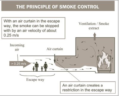
Air curtains may be more appropriate for rail tunnel stations than for the main tunnels, since a closed system with doors in the tunnel where trains enter and exit the station is required for an air curtain to work. The concern is that the doors may accidentally deploy and trains could hit them.
The management of incidents to reduce their duration and impact is a priority for the European countries the scan team visited. These countries have undertaken a variety of activities to effectively manage incidents in tunnels by reducing the time to detect and verify that an incident has occurred, by providing the appropriate response, and by safely clearing the incident while managing traffic flow.
SINTEF described the Norwegian evacuation strategies for road tunnels. These strategies focus on issues from the recent Mont Blanc, Tauern, and Gotthard tunnel fires. In addition, in London in 1987 an event occurred at King's Cross Rail Station that contributed additional data. A modest fire in an escalator developed into a disaster in which 31 people died. Norway has had several tunnel fires in the past few years without loss of life from fire.
In Norway, single-tube tunnels with two-way traffic typically have natural ventilation. In general, portals are the only possible evacuation directions. If on the wrong side of a tunnel fire, a motorist's only chance is to turn the car around and leave. However, airflow direction may dictate the direction of evacuation.
A frequent problem is that motorists do not recognize the seriousness of a fire; they are worried about possessions and make bad decisions on what to do. The high-traffic tunnels in Oslo and Bergen have systems that can override vehicle radios, but radios must be turned on to receive the messages. A question has arisen on whether more information would increase user anxiety about tunnels. Simulations also raise the question of whether people follow posted instructions or a leader.
The Norwegian crisis management procedure for tunnels is to immediately close all tubes when a crash occurs. Users at the incident location must decide whether to sound the alarm, provide first aid, assist in fighting the fire, leave the car and evacuate on foot, or evacuate by car. Rescue personnel must find their way to the right tunnel entrance. Drivers outside the tunnel must find an alternate route. For all events, motorists in the tunnel are their own first rescuers, and self-rescue provides the most effective evacuation strategy. To be able to rescue themselves, motorists need to know the location of emergency exits and should be guided to the direction of the fresh air supply. Preparedness plans should incorporate these considerations.
The overall safety description for the Copenhagen Metro includes planning, heat load calculations and simulations, laws and regulations, and escape route planning below and above the ground. Detailed discussions with emergency professionals and tabletop exercises have taken place to evaluate plans and provide training. Protocol is that the transit system investigates, determines the emergency, and then sends the alarm. Police are the overall incident commanders.
Additional ventilation is provided by louvers in station ceilings that are tied to the ventilation system and can be opened in an emergency. Counterterrorism and threat support are provided by police; weapons of mass destruction (WMD) plans are also being developed. Emergency rescue equipment is pre-positioned at stations; weather services provide warnings where necessary. Fire detectors, smoke detectors, and CCTV are in place. Emergency recovery plans are in place for terrorist events, tunnel collapse, crashes, and removal of failed vehicles by tow, rescue train, or automatic operation. The target detection time is less than a minute for a failed or stranded train, with a maximum 20-minute service interruption. The target response time is 5 to 7 minutes from the time an incident is reported until the response team is onsite. Fencing is provided for access control. An intrusion detection system and CCTV are also used. Data are being collected to review operations and look for needed improvements.
The control room has two operators around the clock: one responsible for the technical installation and road operations and the other responsible for toll station operations and customer assistance. The operators are cross trained. A backup control room is located at the Danish police station in Copenhagen and is being moved to a new location.
Communication is by frequency modulation (FM) radio in the tunnel and trains. The operations center can interrupt the radio channel for emergency announcements. Rescue services have their own radio communication that is common to both Swedish and Danish forces.
For traffic monitoring and control, the Oresund tunnels have fixed cameras every 60 m (200 ft) and portal cameras every 500 m (1,640 ft), for a total of 250 cameras in the open. Barriers are used to close the link, with dynamic signs that give directions for speed, lane use, and messages. No cameras are in the rail side and the shipping lanes are not monitored. Over-height vehicles hit the tunnel about twice a year. Oresundsbro Konsortiet has an agreement with the local coast guard for inspecting areas away from the bridge/tunnel.
Vehicles are monitored with cameras. Images are sent to a server and processed, and an incident can alarm the operator. The camera will automatically switch to the zone in the tunnel where the incident is occurring. The action must be something that moves and then stops; the camera will not find small objects such as bags.
A Belgian company makes the hardware and software that connects to the cameras to identify an incident. The system can produce false alarms near the tunnel entrance. Noise, mast pole vibration, or even an insect on a camera lens can trigger a false alarm. These problems require the operator to concur that the alarm is because of a real incident before action occurs to mitigate. This system has been in place for 5 years and is being continually improved to get better performance, but it is considered unlikely that it will soon be practical to alarm for automatic action. The tunnels have about 10 stopped vehicles per month and these are considered a source for a potential crash since the tunnel has no emergency lanes. The goal is to remove such vehicles within 20 to 30 minutes. So far, no crashes have resulted from stopped cars.
Previously the evacuation concept was to evacuate passengers from an incident train to the opposite railway tube. The new concept to be implemented in 2006 is to evacuate passengers to the motorway tube.
Jet fans in the tunnel system are designed to operate in lines of fans called line control. When a fire occurs, the control room activates more fans. In December 2004, this was changed to group control of fans. Now if a fire occurs, a group of fans on the output of the affected tunnel are turned on to make an over-pressure to keep the smoke in the original tube and the entrance fans in the unaffected tunnel are turned on. This also eliminates the fan noise to improve emergency crew operations.
Escape doors in the tunnel are spaced at 88 m (290 ft). These doors are left unlocked between highways and railway, although there is no handle on the highway side; originally electronic locks were installed but these have been removed. Fire hydrants are also spaced every 88 m (290 ft). On the wall opposite the door is an emergency panel with a fire extinguisher, telephone, and alarm. Users can open the door by pressing a button; when the door is opened, an alarm goes off in the control center directing CCTV to the door. The automatic fire alarm system provides gas extinguishing, water spray, and foam. The tunnel has a fireproof layer on the ceiling and 1 m (3 ft) down the walls. To date, the tunnel has had some smoke from damaged cars and tires but no large fire incident.
Movable barriers are 300 m from the portals and are used for changing traffic direction if one of the tubes is closed for cleaning or an emergency.
Oresundsbro Konsortiet works with three levels in rescue operations. Level 1 is the lowest and has the least needs: Danish assistance only for Denmark and Swedish assistance only for Sweden (e.g., for a small single-car crash). Level 2 is a two-way response; emergency services are needed at the incident as fast as possible. Level 3 is the highest level (e.g., train crash fire or two-way turnout). Several hundred scenarios have been classified into 11 broad scenarios. A car fire on the artificial island would be Level 1, and smoke in the tunnel would be Level 3. No Level 1 is specified for trains.
Language and cultural differences exist between Sweden and Denmark. To make an alarm based on a telephone call and alarm 12 stations is significant. Therefore, Oresundbro Konsortiet bought a computer system in Sweden and loaded 11 incident scenarios. The operator does not determine Level 1, 2, or 3; instead, the operator answers four questions on a dropdown menu and pushes a button. The computer will sequence the equipment, depending on the given scenario. It takes less than 3 minutes for the alarm to be sent out in both languages, saving time and confusion between languages and cultures.
Special rescue equipment needs were assessed. It was determined that a need exists for water systems, infrared cameras for smoke, a fire brigade using motor bikes and water mist tanks to easily get to the fire, and medical assistance.
The 2 years of planning resulted in four books. One book has drawings of the entire link shown from the perspective of rescue workers. The second book has the emergency plan with details on the 11 scenarios, as well as a description of how to organize response to an incident. The third book is an education catalog. The fourth book is for equipment and evaluation of all full-scale exercises. Their first priority is to save lives.
The Citytunnel will have the first underground railway stations in Sweden, and for these stations emergency evacuation plans and regulations will be developed. Because the system will also use Danish trains, Danish regulations were considered along with Swedish regulations. The standards now are to evacuate trains at the stations or outside the tunnel, if possible. Evacuation must be completed before critical conditions are met. Critical conditions are defined as smoke, radiation, and temperature not to exceed a certain limit and visibility to 10 m (33 ft). If the train must stop in the tunnel, the evacuation is to be completed before lethal conditions are met. " Lethal" is defined as conditions not conducive to supporting life. Smoke and fire calculations are compared to the evacuation simulations for the design basis. The intent is for 800 passengers to be able to evacuate to the other track tunnel via the 1.2-m (3.9-ft) wide walkways before lethal conditions occur. A new European standard for high-speed trains is for the train to be able to travel 15 minutes at 80 km/h (50 mi/h) with a fire on board.
Discussions on safety regulations include what circumstances required special traffic restrictions, such as evacuation capacity is limited, control center is down, electrical current is disrupted, or communication systems have failed. Communications are by radio and mobile, regular, and emergency phone systems.
Terrorism and intentional acts of destruction are just now being discussed.
CETU described the approaches used for evacuation of people in French tunnels. The approaches varied with the type of tunnel construction, including cut-and-cover construction, in which stairs could be used to provide cost-effective evacuation and emergency access; two-tube tunnels, in which the adjacent tube provides a means for evacuation through connecting cross passages; tunnels with separate evacuation tube/gallery; and single-tube tunnels. The single-tube tunnel is a much more difficult situation and is generally dictated by the type of tunnel ventilation design. For transverse ventilation, refuge/shelter rooms are built and the fresh air gallery can be used by emergency services for evacuation of users from the shelters; for longitudinal ventilation, no good solution exists. Long single-tube tunnels with longitudinal ventilation are not allowed in France. CETU noted the importance in all instances of adequate signage and other means, such as visual and audio notification, to direct people to the nearest evacuation route. The French directive is to provide emergency exits at 200-m (656-ft) intervals in urban tunnels and 400-m (1,312-ft) intervals in other tunnels.
Video surveillance, used in all manned tunnels, monitors tunnel activity and automatically detects stopped vehicles. Tunnel operations also monitor sensors for nitric oxide (NO), carbon monoxide (CO), airflow, and opacity. Regulations on safety in tunnels provide thresholds for safe operation.
Communication problems between tunnel operators and emergency response agencies include the loss of radio and phone communications in the tunnel because of fire damage to communication facilities (radiating cable) or the effects of ionization of the air. Also, a common problem encountered was the use of different radio systems by emergency response agencies. Harmonization of frequencies or other means need to be provided to ensure communication among all agencies. Also, means must be provided, such as emergency phones, for informing drivers of emergency information, particularly in the event of a fire incident in a tunnel.
CETU has developed a process for safety procedures and documentation that provides a common understanding of the analysis and evaluation required, continuing feedback from tunnel operators, and an upgrade program for existing tunnels. This is provided as a Guide to Road Tunnel Safety Documentation.
CETU officials indicated that they do not consider terrorist threats a significant issue. They look at this in the design phase to see what can be done to detect and deter such incidents. Their primary interest is to detect or, if not possible, to respond quickly, using formal emergency response plans. They developed the following procedures to respond to explosive threats, although it was not clear whether all tunnel operators have adopted them:
CETU has not included provisions or requirements related to radiological, chemical, or biological incidents, apart from those related to dangerous goods incidents. Further studies are required in this area.
The German practice is to provide security or refuge stations at 300-m (984-ft) spacing.
STUVA noted that before the terrorist incidents in New York, Madrid, and London, little attention was given to explosive incidents but that consideration is now given for mass transit applications. There is some application for flood control measures in mass transit tunnels in England and Germany but, because of the expense, not for long-distance train tunnels.
The tunnel has one control room in each portal. Only one control room operates at any one time, and the other is on standby. If a problem occurs at the control room, the control can be instantly changed to the other control room. Two operators are in the active control room and one operator is in the other control room.
Generally, power is supplied to half the system from each end. In the event of a power failure from one end, power can be provided from the other end. The tunnel has an uninterrupted power supply system with no backup generators. Sensors detect the levels of CO, NO, and opacity, with 20 sensors for each.
A space between vehicles of 150 m (490 ft) is mandatory; violators are fined. On a typical day, 1,600 trucks cross the tunnel. Traffic regulations exclude trucks with dangerous goods and trucks made before 1993 because of pollution controls. Checks are made at regulation areas for these exclusions and also to check the truck size. A ticket shows that the size and pollution level are acceptable to cross the tunnel. Truck controls are at both portals. A laser system determines the truck size. The trucks also pass through a thermal detector to identify any unusual heat (see Figure 17). If a problem is detected, the truck will not be allowed to enter the tunnel, and it must be towed. Truck volume is regulated by law, with not more than 240 trucks per hour allowed to cross the tunnel. When the tunnel must be evacuated, the toll operators are in charge of taking small minivans into the tunnels to pick up individuals.
The velocity of air inside the tunnel can be controlled and a zone of zero velocity can be set using the automatic system. A yellow vertical line on the screen in the control room shows air speed equal to zero (see Figure 18. This point can be placed anywhere in the tunnel in 2.5 to 3 minutes to change the location of zero air flow, safely extract smoke, and make emergency evacuation and rescue easier.
Figure 17: Truck thermal detector at the Mont Blanc Tunnel entrance.
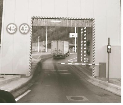
Along the tunnel length are 37 refuge rooms at 300-m spacing, all on one side with a pullout area across from each refuge room (see Figure 19. The refuge rooms are equipped with a video phone and written instructions in three languages that inform individuals that they are safe, that fresh air is being provided, and that the operators know their location (see Figure 20). Signs direct individuals to remain inside the refuge room and not return to the tunnel. Refuge rooms can provide 2-hour protection; escape from the refuge rooms is possible through the fresh air plenum. When there is a fire, overpressure will be initiated in the refuge rooms so that smoke cannot enter. The air exchange in the refuge rooms is 20 m3/h (540 ft3/h). The difference in air pressure between the refuge room and the tunnel is 80 pascals. Smoke is extracted by a longitudinal duct under the roadway.
Eighteen variable message signs are located at 600-m (1,970-ft) intervals to direct people to refuge rooms; the messages are in French, Italian, and English. About 20 barriers are also equipped with small variable message signs. FM radio override is available in the tunnel for the 12 radio stations, 6 French and 6 Italian.
A unique air duct below the roadway is reserved for extraction. Extraction ducts are positioned along the curb line. During a fire, dampers are activated. Four fans are needed and an additional two fans are for backup. Temperature is measured along the entire length of the tunnel with fiber-optic sensors; a red horizontal curve on a screen in the control room shows the temperature curve of the air inside the tunnel in real time. The middle of the tunnel is always at 25 °C. The system will detect a rapid increase in temperature and automatically activate the emergency systems. Jet fans are single speed and reversible. Wet standpipes are used, and a system is in place to keep the pipes warm. There are 200 cameras in the tunnel.
Security procedures now include three blast scenarios:
Currently the scenarios look only at explosives; no WMD procedures have been developed.
Special high-tech trucks protect the Mont Blanc Tunnel in the event of a fire (see Figure 21). These trucks have a steering configuration that allows lateral movement and an extremely small turning radius. Foam can be released from the bottom of the truck, and a hose positioned on its roof can propel water a significant distance. A video camera is mounted on the front of the truck, and the truck is loaded with a variety of safety and firefighting equipment. These trucks, unique to the Mont Blanc tunnel, cost about € 450,000 (US$540,000) each.
Figure 18: " One-button" response for incident management in the Mont Blanc Tunnel.
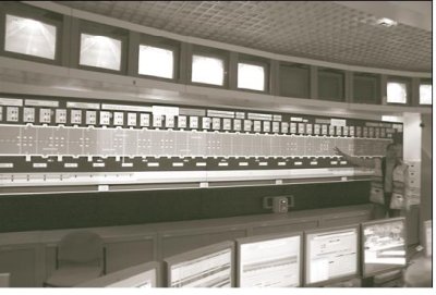
Figure 19: Emergency pullout area across from refuge room in the Mont Blanc Tunnel.
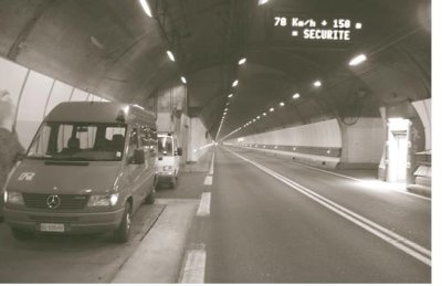
As a result of growing traffic, the sense was that risk was growing and actions were required to address fire issues in the Gotthard Tunnel. Incident management also is a major factor with driver behavior such as U-turns. Firefighting equipment includes trucks with a turntable that can be lowered to reverse engine direction in the tunnel. Smaller equipment is also used for tight situations. Traffic control in Switzerland is handled strictly by Swiss police. Exercises are extremely important and should be conducted in the tunnel.
The Gotthard Tunnel incident plan covers 18 scenarios ranging from minor crashes to leakage of hazardous materials, but none that deal with terror attacks.
Crashes decreased significantly when limits were put on the volume of traffic that can be in the tunnel at any one time. This was done by instituting criteria for distance between vehicles. A minimum spacing of 150 m (490 ft) between trucks and 50 m (160 ft) between cars was effective in reducing traffic crashes from 35 to about 10 per year. Sensors are used to assess the composition of the incoming traffic to control the volume.
Cross passages 40 m (130 ft) long are constructed at 333-m (1,090-ft) intervals. The cross tunnels are separated from the rail tunnels by sliding doors rated for 1,000 °C (1,820 °F) for 90 minutes. If an emergency incident in a rail tunnel makes it necessary for people to escape, they make their way to these cross passages. A metal handrail attached to the tunnel wall on the cross passage side is installed to help people find their way to the cross passage. In general, the rail tunnels are not lighted but they do have emergency lights mounted at eye level and spaced at 12.5 m (41 ft) to help guide evacuees.
Evacuees will be transported out of the tunnel by an evacuation train, which is available on standby for this purpose, or buses, depending on where the evacuees have taken refuge. Until the dual tubes are fully constructed, buses will be used in the incomplete (carcass) tube where available. In another section, the exploratory tunnel that was bored to determine geologic conditions before the main construction began will be used for evacuation.
Figure 20: Mont Blanc refuge room: inside refuge room and instructions posted on wall.
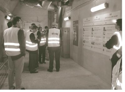
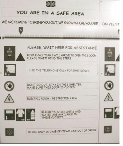
Two redundant operations centers are provided for data transfer and operations control. Tunnel operators are required to be competent electricians and go through a training program of 1 to 2 weeks in the control room and 1 to 2 weeks in the tunnel as part of a maintenance crew before they can work a shift on their own. To prevent data overload for the system and operators, data are sent by exception for changes in baseline condition only; this also speeds up alerts since it reduces processing time.
Firefighting water supplies are located at 106-m (348-ft) intervals throughout the tunnel. Fire extinguishers are located at each water supply box along with a hydrant and in each emergency call box, located every 212 m (696 ft). Hoses with tube length of 100 m (328 ft) are located in all emergency parking niches.
Fire detection is based mainly on a linear heat detector. Smoke detection is automatic via a proprietary system. Automatic detection with CCTV and automatic gas detection are obtained with alarms at the control center that, if confirmed, result in manual activation of fire protocols. Information from an emergency call box, voice, or button, if confirmed in the control center, results in manual activation of the fire alarm. Automatic notification when a fire extinguisher is taken from its holding device, if confirmed in the control center, results in manual activation of the fire alarm.
Two emergency escape exits are located at third points. Cross tunnels are provided every 424 m (1,390 ft) for people and at 1.6 km (1.0 mi) for vehicles. It was again stressed that self-rescue and human behavior in the first 10 minutes of the incident are critical for survival.
Rambøll uses a risk-based approach to safety inspection and maintenance. The trend is to use ongoing monitoring of structural condition. Rambøll staff track the data from their principal (comprehensive) periodic inspections. They accurately record what was done (type of equipment used, etc.) in the inspection so they can evaluate the results properly. With this approach, started in the 1990s, they are accumulating records of the progression of structural deterioration. They are using the data to develop deterioration modeling to determine the existing safety level and ensure that a minimum required level is maintained. The purpose is to optimize the use of available funds, extend the service life of the facility, and minimize traffic disruption.
Nondestructive testing for corrosion is an important method for obtaining data to use for deterioration modeling. Corrosion sensors in combination with online monitoring systems are being used to enable better assessments of condition and also provide the ability to monitor areas of the structure that are difficult or impossible to access.
The police authority has responsibility for road traffic and restrictions for maintenance. Oresundsbro Konsortiet made an agreement with the police authority on how to restrict traffic for maintenance that allows the organization to apply its own traffic restrictions.
The primary maintenance plan is the Link Works Programme (LWP). The LWP is updated every week. The traffic department maintains the plan and keeps track of the number of people onsite. Access is allowed only with a job number from LWP. A crew member notifies traffic control when the crew leaves the site. Traffic costs are related to job numbers. All money related to work can be related to this job number.
Oresundsbro Konsortiet is now putting all maintenance planning into a central database called Maximo developed by Maintec, a Danish company. The database has 5,000 objects, but not all objects from all contractors are identified. Inputting costs is not required because of the concern that other contractors might see the numbers.
One-lane closure is used for maintenance work. Skylifts are not allowed in the tunnels. Only scissor lifts are allowed. Twice a year, the tunnel is closed and 150 people work at night. Inside and outside, variable message signs are used for lane closures.
The motorway tunnels are washed every 3 months, one side at a time. The process takes 2 weeks. Sensors in the pavement monitor the temperature, which is typically 8 to 10 °C (46 to 50 °F). Weather stations with pavement sensors are at portals.
Maintenance is performed with the help of automated data management systems that record and save specified information for status and analytical purposes and that also provide self-diagnostic functions to identify and locate faulted devices. The goal is to establish a preventive maintenance program using information on mean time to failure (MTTF) for systems, subsystems, and components. CETU indicated that this was difficult to apply because of the vast number of different devices and suppliers as well as the general lack of MTTF information for application in road tunnels.
Figure 21: High-tech firefighting trucks for the Mont Blanc Tunnel.
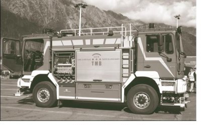
A public-private partnership made the new E39 highway near Tronheim in Norway possible. The route has six rock tunnels and one cut-and-cover tunnel. Video surveillance is used in the two longest tunnels. Speed sensors are installed in the tunnels, and one operations center enables operators to monitor all of the tunnels and control tunnel access from one location. The tunnel has had zero lost time because of crashes.
This public-private partnership enabled the project to be constructed in 26 months. It was estimated that if the project had been done under the normal method with the Norwegian Public Roads Administration proposing, designing, and contracting the construction, it would have taken perhaps 5 years longer. The partnership- including the Public Roads Administration; Orkdalsvegen AS, the financier operator; and Skanska, the constructor-uses the unique capabilities of each to carry the elements of risk in those parts of the work where each has the greatest ability to limit the risk. Sharing risk allows for greater innovation and flexibility to deal with problems as they arise.
Orkdalsvegen will operate the facility for 25 years. The Public Roads Administration will collect toll revenues and make large payments to Orkdalsvegen for the first 3 years and lesser ones for the remaining 22 years. The payment plan allows Skanska to be paid for the construction, Orkdalsvegen to receive a positive return on its investment, and the Public Roads Administration to meet the public's demand for an improved highway system. The arrangement also encourages quality in workmanship; Orkdalsvegen is responsible for maintenance for 25 years, so it benefits greatly from sound construction and low life-cycle costs.
The Citytunnel E201 Tunnels and Triangeln Station in Malmo are owned by the National Rail Administration and operated by private companies. Different packets of work are split up among different contractors. It is a SEK2.4 billion (US$300 million) design-build contract with schematic design by the client.
For the construction procurement, the owner will purchase two tunnel boring machines that the civil works contractor will use to simultaneously drive two tunnel bores. One civil works contractor is responsible for all of the civil works and coordination with the other train operation contractors.
The civil works contract will be a design-build contract with a shared-risk approach to the geotechnical conditions, which are supplied by the owner. A negotiation process for additional payment will take place if conditions change significantly. No independent engineering checks are required, although an independent checker reviews drawings and methods for temporary works that could result in damage. The contractor will prepare his own construction schedule and is responsible for quality control. The owner audits the paperwork but does almost no quality assurance. Payment is made as the contractor reaches milestones, with very few measurements taken. The owner puts its trust in the suppliers.
Partnering is limited under legislation for public procurement. However, the owner has participation in procurement of key equipment, a joint seminar for risk identification, input on temporary works designed to minimize risks, and regular joint construction meetings on critical activities such as water drawdown. The primary construction risks are expected to be groundwater, settlement, and delays due to environmental concerns about chemicals used on the project. The risk-management principles are in accordance with an EU and United Kingdom document entitled A Code of Practice for Risk Management of Tunnel Works, as done for the Oresund Link.
| << Previous | Contents | Next >> |

