U.S. Department of Transportation
Federal Highway Administration
1200 New Jersey Avenue, SE
Washington, DC 20590
202-366-4000
Ontario has built concrete pavements since the 1930s, with the 1960s and early 1970s a period of major expansion of the freeway network. Many of Ontario's major freeways were originally constructed in concrete. This era of expansion was followed by one of reduced highway construction activity and a loss of experience and expertise because of the retirement of many older engineers. A highway technology program launched in the 1980s formed the basis for the pavement design and construction practices used in Ontario today.
The standard concrete pavement in Ontario is a dowelled, jointed plain concrete pavement with a 14-ft (4.25-m) widened outside lane. Perpendicular transverse joints are randomly spaced at an average 14 ft (4.25 m). Concrete pavement thicknesses range from 8 to 11 in (200 to 280 mm). The thickness design is based on both the 1993 AASHTO Guide for the Design of Pavement Structures and the Canadian Portland Cement Association's mechanistic-empirical rigid design method. Since 1992, a 4-in-thick (100-mm-thick), asphalt-treated, open-graded drainage layer (0.75-in (19 mm) top size crushed stone, 1.8 percent asphalt cement) has been used for pavements on the highest-volume routes. Untreated open-graded layers, 6 in (150 mm) thick, are allowed on lower-volume routes. The design standards allow open-graded cement-treated base as an option, and a project to be built in 2007 on Highway 410 will be the first with this type of base. Full-length perforated plastic pipe subdrains are placed in a filter-wrapped trench in the shoulder area, backfilled with open-graded aggregate.
After trying various concrete pavement designs over the past 50 years, the province of Québec now builds both jointed plain and continuously reinforced concrete pavements. In the 1950s and '60s, Québec built 9-in (230-mm) jointed reinforced concrete pavements, but had problems with joint deterioration. In the 1970s, Québec switched to an undowelled jointed plain concrete pavement design, also with 9-in (230-mm) slabs, but these pavements experienced problems with joint faulting and frost heave. In the 1980s, Québec built 8-in (200-mm) jointed plain concrete pavements, which experienced construction, structural, and frost heave problems. By the early 1990s, nearly all of Québec's concrete highway pavements were in need of reconstruction.
In 1994, two standard concrete pavement designs were adopted by the Québec Ministry of Transportation (MTQ). The first is JPCP, with the slab thickness designed for truck traffic over a 30-year design period according to the 1993 AASHTO Guide for the Design of Pavement Structures(21) method (using 50 percent reliability), and a total pavement thickness adequate for protection against frost heave. Truck factors (ESALs/truck) have been developed to characterize expected truck traffic for pavement design purposes. Typical JPCP slab thicknesses built according to the current standard are between 10 and 13 in (250 and 325 mm). Jointed concrete pavements are dowelled, with sealed joints, and rest on 6 in (150 mm) of granular base and a variable thickness of granular subbase for frost protection. Since making these changes to the standard JPCP design in 1994, fewer than 1 percent of the JPCP slabs constructed have exhibited cracking. The main distress type in these pavements is joint and corner spalling, usually addressed by partial-depth repair.
The second standard concrete pavement design used in Québec is CRCP. The first experiment in CRCP, a 1.2-mi (2-km) section, was built on Highway 13 in 2000. This pavement was a 10.6-in (270-mm) slab on granular subbase with 0.70 percent black steel. The right shoulder was paved as JPCP, and the left shoulder was paved as CRCP. Six other CRCP projects have been built in Québec since 2003. The 5.6-mi (9.1-km) section on Highway 40 is typical of these. It has an 11-in (285-mm) slab on an open-graded cement-stabilized layer, 0.76 percent galvanized steel, and JPCP shoulders. A 30-year design period is also used for CRCP. Uncertainty about the potential for steel corrosion in CRCP is a concern because Québec applies 44 to 66 tons (40 to 60 metric tons) of deicing salt per two-lane km to its roadways every winter (about two to three times as much salt as Illinois uses, for example).
Germany began building concrete roads in the late 1880s and in 1934 started using concrete pavement extensively in the construction of its motorway (expressway) system. Between 1935 and 1939, some 2,200 mi (3,500 km) of motorways were built in Germany with a pavement cross-section of about 9 in (220 mm) of wire-mesh reinforced concrete on 4 in (100 mm) of sand base course, and expansion joints every 33 to 66 ft (10 to 20 m).
Until the early 1960s, Germany built primarily jointed reinforced concrete pavements on unbound base courses, using expansion joints and transverse contraction joints spaced 25 to 33 ft (7.5 to 10 m) apart. The standard jointed plain concrete pavement design for motorways in Germany was changed in 1972 to one without expansion joints and with transverse contraction joints spaced 16 ft (5 m) apart on cement-treated or asphalt-treated base. The first slipform paving on German motorways was done in 1982.(22)
Today, about 25 percent of Germany's 7,500 mi (12,050 km) of motorways are concrete pavements. Motorways make up about 2 percent of Germany's total road network (389,500 mi (626,800 km)), but their investment value is estimated at about 26 percent of the total value of Germany's roadway network, about US$342 billion (€250 billion) in 2003.
The average traffic load on German expressways is about 8,000 trucks per day, although some routes carry three to four times that. The axle load limit is 11.5 tons (10.4 metric tons) for German trucks and 13 tons (11.7 metric tons) for trucks from neighboring countries. These heavy traffic volumes and loads are a major reason for using concrete for many of the expressway resurfacing and new construction projects in the former German Democratic Republic.
Germany uses a catalog for selecting concrete pavement slab thickness and other details as a function of traffic level and other factors. This catalog(23) is updated about every 10 years (most recently in 2001). The standard designs are based on the forecasted traffic loads over a period of 30 years. The number of standard axle loads through the 30th year is termed the load value, B, and this value determines the construction class, which in turn determines the pavement layer thicknesses required. Of the seven construction classes defined in the German catalog, the highest class, labeled SV, corresponds to 32 million or more standard axle loads over 30 years. Motorways are assumed to fall into the SV construction class.
The total pavement thickness to be constructed, according to the requirements of the German catalog, is the sum of the thicknesses of the concrete surface, base course (cement-treated, asphalt-treated, or untreated), and frost protection layer. The thickness of the frost protection layer depends on the climate of the region and the frost sensitivity of the subsoil. The typical total pavement thickness is 22 to 35 in (55 to 90 cm). Figure 18 illustrates the motorway (construction class SV) cross-section designs indicated in the German design catalog for three base types (cement-treated, asphalt-treated, and untreated) for a location requiring a total pavement depth of 35 in (90 cm) for frost protection. Figure 19 shows a portion of Germany's design catalog page for concrete pavement design alternatives.
Figure 18: Concrete pavement design alternatives in German catalog for motorway traffic (construction class SV, >32 million axle loads over 30 years) and 35 in (90 cm) total depth (1 in = 2.54 cm).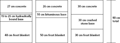
Figure 19: Portion of Germany's design catalog page for concrete pavement design alternatives.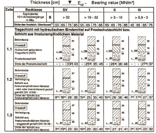
Germany's pavement design catalog now requires the use of a geotextile to separate a concrete slab from a cement-treated base. In the past, Germany's standard design for cement-treated base depended on these two layers being bonded and the cement-treated base being notched at locations matching the joints in the concrete slab to facilitate controlled cracking in the base. The required concrete slab thickness for the new cement-treated base alternative is 10.6 in (27 cm); it was 10.2 in (26 cm) for the old design with a bonded base. The design compressive strength of the cement-treated base is 2,100 pounds per square inch (psi) (15 megapascals (MPa)) under a concrete slab and 1,000 psi (7 MPa) under asphalt layers.
The geotextile used with the cement-treated base design alternative is a nonwoven polyethylene or polypropylene, 0.2 in (5 mm) thick. This fabric is attached to the cement-treated base before the concrete slab is placed, and care is taken to prevent construction traffic from damaging the geotextile once it has been laid. Figure 20 shows a core through a concrete pavement with cement-treated base and geotextile interlayer.
Figure 20: Concrete, cement-treated base, and geotextile interlayer used in Germany.
The unbound base used with the third design alternative is crushed aggregate with a minimum thickness of 12 in (300 mm), and a gradation sufficiently open to prevent water that enters the pavement structure from accumulating near joints and cracks and pumping out under traffic loads.(24)
For all three JPCP design alternatives, the joint spacing is 16 ft (5 m). Dowel bars at the transverse joints are spaced every 10 in (250 mm) in the wheel paths and every 20 in (500 mm) outside of the wheel paths. The dowels are plastic-coated steel, with a diameter of 1 in (25 mm) and length of 20 in (500 mm). Deformed, plastic-coated tie bars, 0.8 in (20 mm) in diameter and 31.5 in (800 mm long), are used at the longitudinal joints. Five tie bars per slab are used in longitudinal construction joints, and three tie bars per slab are used in longitudinal contraction joints. Concrete slabs for the driving lanes are paved wider than the painted traffic lane to reduce stresses and deflections at the slab edges. The joint layout details are illustrated in figure 21.
Figure 21: Joint layout details for standard German concrete pavement design.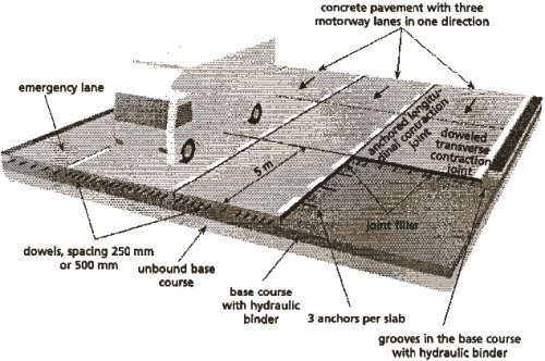
Austria's concrete pavement design and construction standard, RVS 8S.06.32, was developed and is kept up to date by the Concrete Pavements Working Group of the Austrian Association for Research on Road, Rail, and Transport (Österreichische Forschungsgesellschaft Strasse–Schiene–Verkehr, FSV).(25) This standard dictates the thicknesses of concrete surfacing and underlying layers to be used for each of six different traffic load classes, as illustrated in figure 22. The highest traffic loading class, the "S" class (18 to 40 million design axle loads), is used for motorways. The standard concrete pavement design constructed in Austria for motorways and other roadways in the S traffic loading class is a jointed plain concrete pavement, 10 in (25 cm) thick, on 2 in (5 cm) of bituminous interlayer and either 18 in (45 cm) of unbound base or 8 in (20 cm) of cement-stabilized base. The joints are spaced at 18 to 20 ft (5.5 to 6 m).(26)
Figure 22: Portion of Austria's design catalog page showing concrete pavement layer thicknesses for different traffic loading levels. Motorways are in the S class.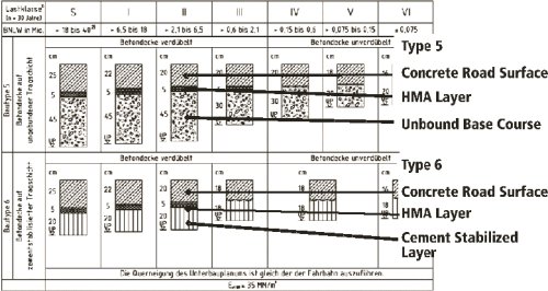
All concrete pavement surfaces in Austria are built in two lifts, with virgin or recycled concrete aggregate used in the lower 8 in (21 cm) and more wear-resistant aggregate used in the upper 1.5 in (4 cm). The surface is given an exposed aggregate texture. Details of the two-lift construction process and exposed aggregate surface texturing process are described in Chapter 4.
Dowels in the transverse joints are 1 in (26 mm) in diameter and 20 in (500 mm) long. Dowels are spaced more closely in the traffic lane wheelpaths and farther apart between the wheelpaths. Tie bars in the longitudinal joints are 0.55 in (14 mm) in diameter and 27.5 in (700 mm) long, and spaced 6.5 ft (2 m) apart (three tie bars per slab). Sealant reservoirs are sawed 0.3 in (8 mm) wide in both transverse and longitudinal joints; preformed seals are used in transverse joints and liquid sealant is used in longitudinal joints. Figure 23 shows details of the standard Austrian concrete pavement design.
Figure 23: Standard Austrian jointed plain concrete pavement design (1 in = 2.54 cm).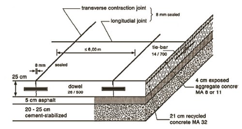
Belgium has a long history of concrete road construction. The Avenue de Lorraine in Brussels, constructed in 1925, remained in service until 2003, when it received a concrete overlay. This pavement, on an old forestry road connecting southern Brussels to the highway, was just 6 in (15 cm) thick.
Examination of Belgian design details from the 1930s reveal a recognition of the influence of edge loadings on concrete pavement cracking, as shown in figure 24. The design alternatives at the time were a minimum thickness of 5 in (12 cm) for slabs constructed on a gravel base and a minimum thickness of 6 in (15 cm) for slabs on grade, with the slab 2 in (5 cm) thicker at the edges for either case.
Figure 24: Thickened-edge concrete pavement design used in Belgium in the 1930s.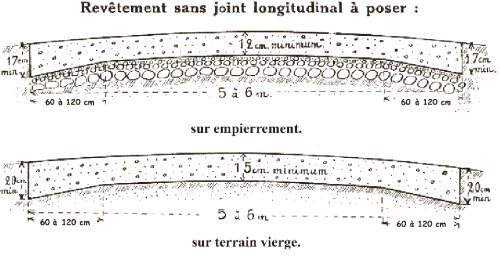
The Avenue de Lorraine is not unique; Brussels has many examples of concrete roads that have served traffic for 50 years or more. Figure 25 shows a photo of a concrete pavement built in 1950 on the road between Leopoldsburg and Hechtel that is still in service today.
Figure 25: Concrete pavement in Belgium still in service after 55 years.
Problems over the years with slab cracking because of excessive length, as well as joint spalling and faulting, led to incremental changes in the standard Belgian concrete pavement design. Today, jointed plain concrete pavements in Belgium are constructed with a joint spacing between 13 and 16 ft (4 and 5 m), dowels in the transverse joints, and a rigid base layer.
Belgium built its first continuously reinforced concrete pavement in 1960. The steel content in this pavement was between 0.3 and 0.5 percent. The second CRC pavement in Belgium was built in 1964, and the first CRC overlay was built in 1968.
In the late 1960s, a team of Belgian engineers of the Road Authorities and the Belgium Cement Research Centre made a field trip to the United States, where by that time more than 2,400 mi (3,800 km) of CRCP had been constructed. American CRCP design and construction technologies were adapted to Belgium and used to construct a large portion of the Belgian motorway network in the 1970s.
Between 1970 and 1977, CRC pavements were built 8 in (20 cm) thick, with 0.85 percent steel placed at a depth of 30 percent of the slab thickness. A 2.4-in (6-cm) bituminous separation layer was used between the concrete slab and the lean concrete base, which was built over a drainable granular layer.
In 1977, the steel content in the standard Belgian CRCP design was reduced to 0.67 percent, and this was the design used until 1991. The depth of steel placement was changed from 2.4 in (6 cm) to 3.5 in (9 cm). The concrete slab and lean concrete base thicknesses remained 8 in (20 cm), but the bituminous separation layer was eliminated. The layer thickness reductions, steel reduction, and elimination of the bituminous separation layer were all done to reduce costs.
A typical problem of the CRC pavements built with these design details was erosion of the lean concrete base, pumping of water and fines from the longitudinal joint (see figure 26), and the formation of punchouts. A large research study in 1992 identified several deficiencies in the then-current design practices for CRCP.
Figure 26: Pumping of fines from lean concrete base under Belgian CRCP built between 1977 and 1991.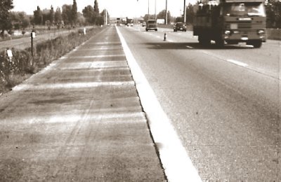
As a result, the 2.4-in (6-cm) bituminous separation layer was reintroduced to the standard CRCP design, the standard CRCP slab thickness was increased to 9 in (23 cm), and the steel content was increased to 0.72 percent. In 1995, the steel content was changed to 0.76 percent. This change in the reinforcement design was made not for engineering reasons but because of the disappearance of 0.7-in (18-mm) bars from the market. The 0.76 percent steel content, as well as the 9-in (23-cm) slab thickness, 2.4-in (6-cm) separation layer, and 8-in (20-cm) lean concrete base, remain Belgium's standard CRCP design today for the construction class corresponding to the heaviest traffic loads and a design life of 30 years.
The standard JPCP design for the same construction class and 30-year design life is 10 in (25 cm) of concrete on a 2.4-in (6-cm) bituminous separation layer and 8 in (20 cm) of lean concrete. For both JPCP and CRCP, these standard designs produce pavements that easily meet the 30-year design life and survive 40 years or more without requiring major intervention.
In the 1950s, concrete pavements built on the Netherlands' motorway system were undowelled JPCP. Dowelling of transverse joints in JPCP became the practice in the Netherlands in the 1960s. While about half of the existing concrete pavements on Dutch motorways are JPCP, in recent years, almost all new concrete pavements on the motorways have been built as CRCP.
Before 2005, concrete pavement construction in the Netherlands used materials and methods specifications. A change to end-result specifications occurred in 2005 and, as discussed earlier, the current trend in concrete pavement construction contracting is the use of design-build contracts with a 7-year post-construction warranty period.
The Netherlands uses a mechanistic-design software package called VENCON for concrete pavement design.(27, 28) The Netherlands also has a pavement design catalog. Typical cross sections and other details for pavements for different roadway functional classes and traffic levels are available in the Dutch Cement Concrete Pavement Manual—Basic Structures.(29)
Based on field measurements, a preset distribution of axle types is used in the pavement design software. The total number of axles applied is assumed to be 39 percent dual-wheel front axles, 38 percent dual-wheel rear axles, and 23 percent wide-based single-wheel axles. There are plans to introduce super wide-base single-wheel axles in the near future. Default axle load spectra (distribution of axle loads by weight) are also assumed in the program, depending on the road class.
Jointed concrete pavements are designed according to a slab-on-dense-liquid model (springs with stiffness represented by a k value). Stresses in the concrete slab are calculated using Westergaard's 1948 equations, modified by van Cauwelaert's multilayer slab model to include consideration of a treated base. Thermal stresses in the concrete slab are recalculated using Eisenmann's equations. A table of typical degrees of deflection load transfer for different types of joints and bases is used to calculate an effective reduction in applied load. A fatigue damage accumulation model is used to determine the life of a candidate slab thickness.
A tensile stress model developed at Delft University is used to determine the required steel content for CRCP. Design lives of 30 to 40 years are typically used for CRC pavements. A typical design would be 10 in (25 cm) of CRC with a 2-in (5-cm) porous asphalt surface, 2.4 in (6 cm) of bituminous material below the CRC slab to separate it from the base, and 10 in (25 cm) of base composed of a mix of crushed concrete, crushed masonry, and a hydraulic binder. These treated layers would be constructed on a roadbed of at least 16 in (40 cm) of sand. (Frost penetration depth is not so much the issue in the Netherlands as the minimum height of the roadway above the water table. The bottom of the subbase must be at least 31.5 in (80 cm) above the highest recorded level of the water table.)(30) The longitudinal steel content in a 10-in (25-cm) CRC slab would be 0.70 percent. Figure 27 shows longitudinal joint details.
Figure 27: Longitudinal joint layout details for concrete pavement in the Netherlands.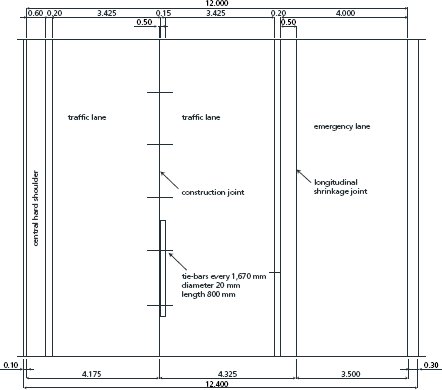
An empirical design approach was used for CRC pavements built in the United Kingdom before 1975. According to this approach, a minimum thickness was used up to a certain level of traffic, and above this level, the required thickness was a function of the traffic level. The required thickness was based on an assumed concrete strength of 5,800 psi (40 MPa), and no credit was given for higher concrete strength. New design curves for CRCP have recently been developed, based on the design flexural strength of the concrete rather than a fixed strength value.(31) The longitudinal steel content used is 0.6 percent.
| << Previous | Contents | Next >> |

