U.S. Department of Transportation
Federal Highway Administration
1200 New Jersey Avenue, SE
Washington, DC 20590
202-366-4000
Sweden uses a number of innovative traffic control devices to improve safety at signalized intersections. Some measures have been in place for some time and have been shown to be effective, while others are new and considered experimental.
Perhaps the most intriguing and comprehensive intersection safety technique being used by the Swedes is a system called LHOVRA.10 The LHOVRA system consists of a series of detectors placed along the approach to an intersection. The detectors determine vehicle type and speed at various locations along the approach and adjust the signal timing by increasing the yellow change and all red clearance intervals to minimize the number of vehicles caught in the dilemma zone (Figure 4-1). LHOVRA was originally designed to accommodate heavy trucks, but the system appears to be flexible and can be programmed to optimize several features.
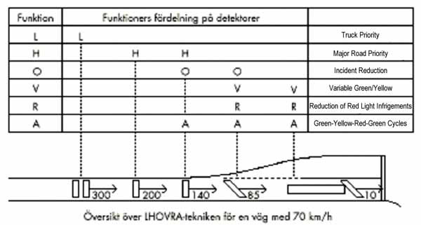
Figure 4-1. Detector layout and relationship for LHOVRA system.
The LHOVRA system has been successfully implemented and is most effective at high-speed rural intersections, particularly where heavy truck traffic is a safety concern. SNRA has completed before-and-after studies at intersections where LHOVRA has been implemented, and the results are promising. Figure 4-2 summarizes before-and-after studies in which incident reduction (the O function in LHOVRA) was the primary goal.
Type of conflicts*) and the number with the O-function
*) with conflict technique analysis methodology
| Before LHOVRA = Trad. signals |
With LHOVRA | |
|---|---|---|
| Rear-end conflicts | 30 | 7 |
| Miscellaneous | 4 | 3 |
| Total | 34 | 10 |
Figure 4-2. Summary of before-and-after studies of implementation of LHOVRA system.
A number of issues should be considered before the LHOVRA system is implemented, and a location study must be completed to ensure that the technology will function properly and improve intersection safety performance. It is possible for the technology to be used improperly by road users (motorists and pedestrians).11 A comprehensive report on developing and implementing LHOVRA is available through SNRA, "Signal Control Strategy for Isolated Intersections" (publication 1991:51E). For more information, contact Alf Peterson, SNRA. See Appendix C for contact information.
Stockholm recently converted all of its signals (more than 10,500 heads and 27,000 lenses) to LED. It is the largest city in the world to have made the complete conversion, and it did so in response to the national government's offer of large grants for energy conservation. The conversion to LED, driven by the need to conserve energy, cost the equivalent of U.S. $5.3 million (almost all paid by the national government) and is estimated to save about U.S. $870,000 a year in energy costs. The LEDs have an estimated life of 10 years, and the investment is expected to be paid off in six years. While no data on the safety advantages is available yet, LED lighting improves visibility and public response has been positive.12
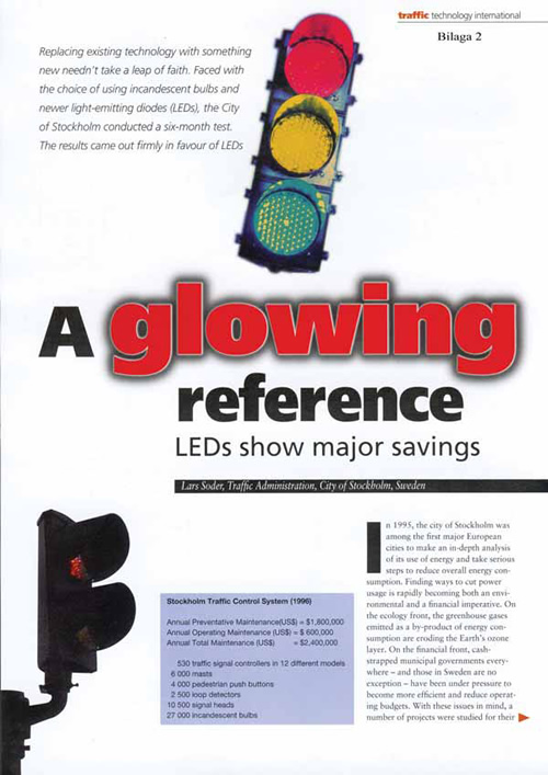
Figure 4-3. Report summarizing conversion to LED lighting in Stockholm, Sweden.
Stockholm is experimenting with handheld transponders that extend green signals at signalized crossings for pedestrians. When the transponder is held up to a polemounted sensor, the green period is extended, allowing a group of children, for example, to cross the street completely. Transponder use is limited to kindergarten teachers and crossing guards in selected school zones with large numbers of students. Responses from test groups have been positive, but the city is concerned about receiving a flood of requests from other special-user groups interested in seeing the technology implemented on a broader basis. Use beyond school zones would have a significant negative impact on traffic flow synchronization and intersection operations.13
Sweden is also experimenting with portable variable-message signs in school zones. When a motorist approaches the school zone traveling at a speed greater than the posted limit, the sign lights up with a message that indicates the motorist is speeding in a school zone.
Many pedestrian crossings in Stockholm are equipped with acoustic indicators. The devices serve two purposes. First, they reinforce the visual crosswalk indicators by emitting a fast ticking sound during the green pedestrian phase, an even-faster ticking during the pedestrian-clearance phase, and a slow ticking during the red pedestrian phase. Since the same ticking sounds are used on both streets, it is essential that the speakers emitting the sound be aimed directly at the pedestrians waiting at each crosswalk. The team believes this is a particularly effective approach (superior to the chirping sounds used in the United States). Second, they provide clear "walk" and "don't-walk" indications for the visually impaired. Some pedestrian-crossing push buttons are equipped with a special locator tone that helps the visually impaired locate the button (Figure 4-4).
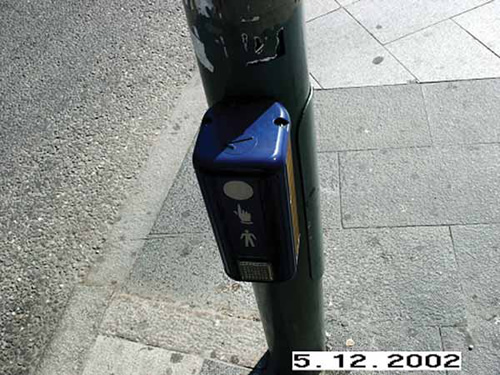
Figure 4-4. Pedestrian push button equipped with acoustic locator tone in Sweden.
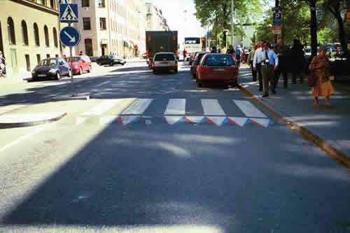
Sweden has also implemented the use of raised and "virtually" raised pedestrian crossings to slow vehicles approaching a crossing. Raised crossings have been somewhat successful in reducing vehicle speed and increasing the likelihood a motorist will yield the right-of-way. Surveys show that pedestrians generally favor the raised walk. One exception is the visually impaired, for whom detecting a raised crossing is difficult.
Virtually raised pedestrian crosswalks are painted on the roadway surface and give the optical illusion of a raised surface (Figure 4-5). This approach is most effective and appropriate in locations where the majority of motorists are unfamiliar drivers.
Automated enforcement techniques have been shown to be effective in Germany. The Germans use photo enforcement to control speed on roadway segments and high-speed intersection approaches. As discussed in Chapter 3, Germany does not signalize intersections with approach speeds greater than 70 kilometers per hour. For situations in which signals are required on higher-speed roadways, the speed limit is reduced before the intersection. This practice is effective, however, only if motorists obey the reduced-speed limits.
To address this need, Germany has successfully applied photo enforcement techniques to slow traffic and reduce red-light running. Officials identified two keys to successful application. First, the public must be aware that the cameras are in place. Second, a substantial penalty must be associated with disobeying the posted speed or running a red light. German speed-enforcement cameras are highly visible, signs warn of photo enforcement, and public messages are broadcast to make motorists aware that the equipment is being used. The Germans are studying the effectiveness of the cameras, but based on preliminary observations and before-and-after studies at several intersections, the reduction in the number and severity of accidents has been dramatic. Officials noted that in some cases, though, the number of less-severe rear-end accidents has increased because motorists are not willing to chance running a red light by speeding through an intersection. Photo enforcement has also been shown to reduce vehicle speed on roadway segments with high-speed-accident problems. Problems with photo enforcement have included vandalism and equipment tampering at some locations.
Based on the results to date, the Germans want to expand the use of photo enforcement as part of their safety program, but the cost of camera equipment and the labor required to process photographs and issue citations has limited the number of locations that can be equipped. (Officials noted that initially cameras can generate substantial revenue, but once the public becomes aware of them, the number of violations drops dramatically, resulting in less revenue.) To broaden the use of photo enforcement and control costs, the Germans are evaluating rotating cameras among multiple sites. The approach is to construct the photo enforcement infrastructure (including the highly visible pole-mounted camera box, signs, etc.) at multiple locations and move a camera randomly from site to site. They anticipate that a single camera could control traffic at 15 locations. Portable Radar and Message Signs The Germans also use portable radar and message signs before intersections with speed-related accident problems. A portable radar detector records motorists' speeds, and if they are traveling above the posted limit, a message that tells them they are traveling too fast is activated. This technology has been shown to reduce speeds by 5 to 8 kilometers per hour. Signal Back Plates At intersections where signal visibility has been determined to be a contributing factor to high numbers of accidents, back plates are sometimes used to enhance the visibility of the traffic signals (Figure 4-6).
The Germans also use portable radar and message signs before intersections with speed-related accident problems. A portable radar detector records motorists' speeds, and if they are traveling above the posted limit, a message that tells them they are traveling too fast is activated. This technology has been shown to reduce speeds by 5 to 8 kilometers per hour.
At intersections where signal visibility has been determined to be a contributing factor to high numbers of accidents, back plates are sometimes used to enhance the visibility of the traffic signals (Figure 4-6).
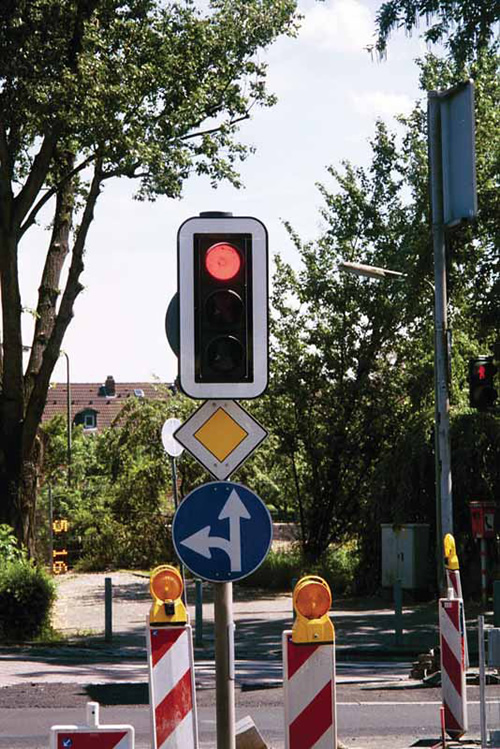
Figure 4-6. Traffic signal with back plate in Germany.
Special care is taken to protect pedestrians at locations with a sight obstruction between motor vehicle traffic and a pedestrian crossing or where a pedestrian crossing phase conflicts with a motorized vehicle phase (Figure 4-7). For example, if an obstruction exists in the sight triangle of an intersection and a right-turning vehicle cannot see the pedestrian crosswalk, a yellow flasher warns the motorist of the possibility of pedestrian traffic around the corner.
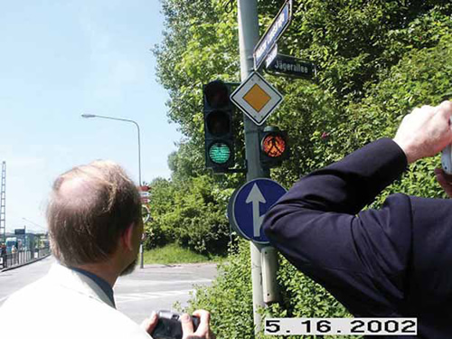
Figure 4-7. Supplemental signal warning rightturning motorists about pedestrians
Audible pedestrian signals are used to supplement signal indicators. The audible signals are designed with a variable-volume feature controlled by the surrounding traffic noise. As the level of traffic noise increases, so does the volume of the audible crossing signal (Figure 4-8).
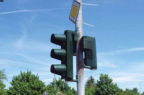
Figure 4-8. Pole-mounted audible signal in Germany.
The use of traffic control devices in the Netherlands is focused largely on the desire to control traffic speed. The Dutch strive to provide visible and easily understood traffic signal controls by doing the following:
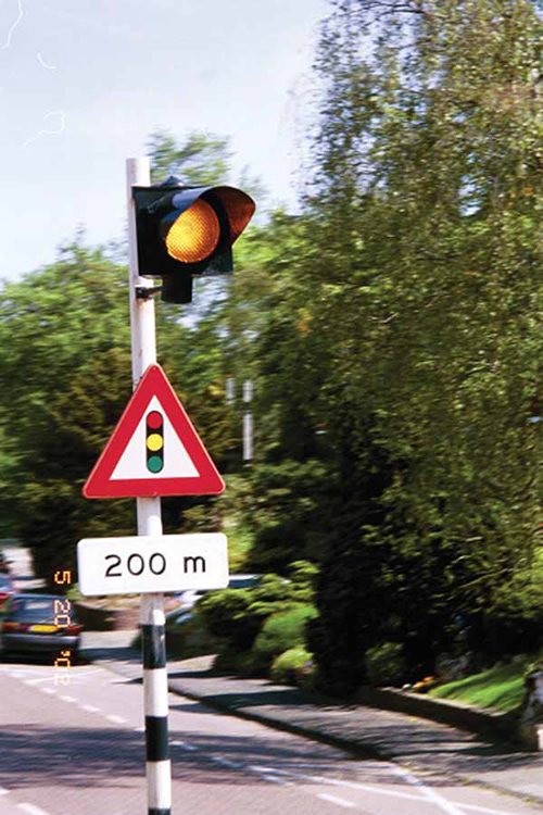
Figure 4-9. "Signal ahead" warning sign in the Netherlands.
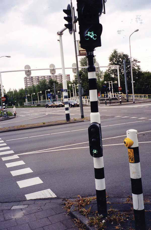
Figure 4-10. Signal poles with high-contrast stripes.
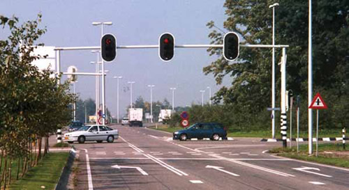
Figure 4-11. Large back plate bordered by white stripe.
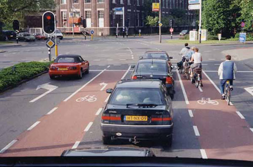
Figure 4-12. Colored pavement used to distinguish bike lanes in the Netherlands.
Officials recognize, however, that optical messaging alone is not enough to eliminate accidents at signalized intersections and that they must lower speeds to reduce the severity of accidents.
Photo enforcement to reduce speed and red-light running is used extensively in the Netherlands and has been shown to be effective. The program's success is based largely on visibility and public awareness. In Rotterdam, cameras are marked with red and blue stripes and are clearly visible to the public (Figure 4-13). In addition, many intersections with photo enforcement equipment are clearly signed in advance (Figure 4-13). Like the Germans, the Dutch rotate one camera among multiple sites. The Netherlands has 600 to 700 camera posts, with an average ratio of one camera for every four posts. Wet film technology is used to photograph violators. Digital camera technology has been tested, but the lack of secure data lines between the camera installations and police agencies coupled with file size requirements of digital images have made digital imaging prohibitive for now.
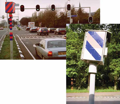
Figure 4-13. Photo enforcement camera for red-light running in the Netherlands.
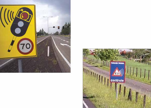
Figure 4-14. Photo enforcement warning signs in the Netherlands.
Studies have shown photo enforcement programs to be extremely effective. After about six months of enforcement, the number of violations drops to nearly zero (Figure 4-15). In cases where the public realizes that a camera is not always in use, the number of violations tends to increase. When such an increase is recognized, the enforcement time at that particular location is increased, and violation rates drop again.
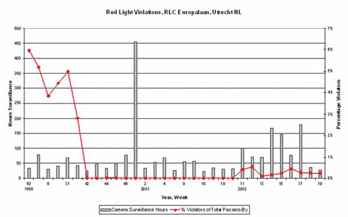
Figure 4-15. Effectiveness of photo enforcement in Utrecht, Netherlands.
To change motorists' behavior, the Dutch have invested considerable time and money in a public awareness campaign aimed in part at photo enforcement goals but more broadly at overall road-user safety.14
The Dutch have not yet concluded studies that confirm the safety effectiveness of the photo enforcement program. The program is viewed as having two phases: the first to change driver behavior and the second to evaluate the impact on safety. Because the Dutch started the program in 1999 and they believe it takes about two years to change motorist behavior, they are just beginning to research the safety effects of photo enforcement.
The Dutch use variable-message signs before high-speed (50 kilometers per hour or greater) intersections to warn motorists that they are traveling above the posted speed limit (Figure 4-16). Often these signs are used in conjunction with clearly marked and signed speed tables located just beyond the stop bar (Figure 4-17). Speed tables, carefully designed so that traffic traveling at or below the speed limit passes over them comfortably, are not safety hazards for traffic traveling over the speed limit. Speed tables are more comfortable than speed bumps for long vehicles (buses, trailers) in particular, but the speed reduction of heavy traffic still remains.15
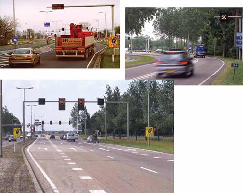
Figure 4-16. Variable message signs on approaches to highspeed intersections in the Netherlands.
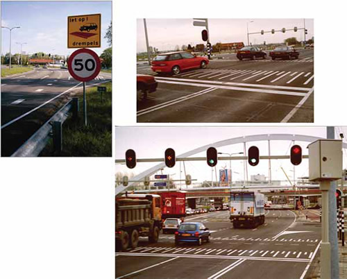
Figure 4-17. Advance warning signs and speed tables at intersections in the Netherlands.
Bicycles are used extensively as regular transportation in the Netherlands, and bicyclists' impact on intersection safety and operation is a primary consideration. The Dutch strive to eliminate conflicts between motorized and nonmotorized traffic (e.g., protected-only phasing) and to reduce wait times for nonmotorized traffic. Most serious pedestrian and bicyclist accidents are a result of crossing against a red signal. To minimize the likelihood of nonmotorized traffic crossing against the red phase, the Dutch have implemented several strategies:
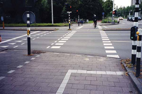
Figure 4-18. Nearside bicycle signals In the Netherlands.
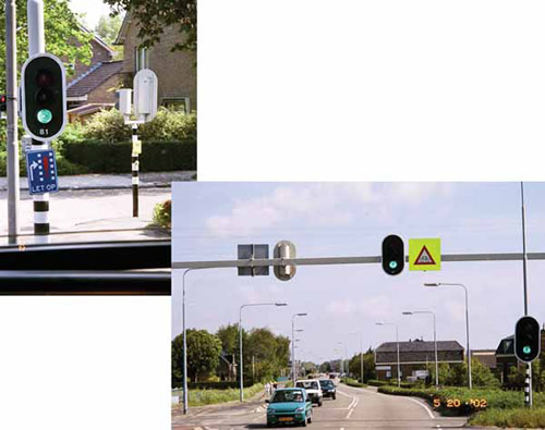
Figure 4-19. Supplemental signing identifying bicycle and pedestrian crossings.
Countdown timers appear to be an effective way of providing positive reinforcement to nonmotorized traffic that the pedestrian timing button has been activated and the signal is operating properly. Several devices are used to convey this message to pedestrians and bicyclists. One is a round countdown signal with 31 lights mounted next to the bicycle indicator (Figure 4-20). At the beginning of the red phase, all 31 lights on the signal are lit. As the green phase approaches, the lights darken one by one to let the cyclist know how much longer until the green phase is activated. A similar indicator surrounds the pedestrian push button (Figure 4-21). The yellow lights surrounding the push button are darkened to let pedestrians know when the wait is ending.
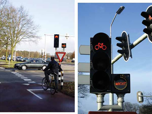
Figure 4-20. Countdown indicator for bicycle crossing.
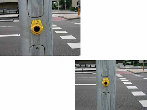
Figure 4-21. Pedestrian countdown indicator on push button.
Most signals in the Netherlands are traffic actuated, and the signal timings vary for each cycle. The rate at which the individual lights go dark varies and is synchronized to the signal timing and operation. The timer starts by calculating the maximum wait times. If a signal group does not get a call for green, the timer accelerates, and when the last light goes out, the signal turns green. Studies have shown the following: • Red-light running by bicyclists has dropped 25 to 30 percent.
Other timers being tested are a digital hourglass timer on the pedestrian signal pole and pavement lights installed in the crosswalk.
At signalized intersections, separate lanes are striped for left- and right-turning bicyclists. Signs are posted to alert drivers to the presence of turning bicycles (Figures 4-12 and 4-20).
Enforcement cameras were first introduced in the United Kingdom in 1991. A number of research studies have proven their effectiveness in reducing traffic accidents.17
An August 2001 study and report prepared for the Department of Transport examined the effectiveness of the cameras and the issue of cost recovery on a pilot basis.18 The study found that sites with cameras had an average of 35 percent fewer accidents and 47 percent fewer fatalities and serious injuries. A number of sites indicated that camera enforcement was particularly successful in reducing accidents between vehicles and vulnerable road users (i.e., pedestrians, particularly children). The study included a public opinion poll that found that the public was generally supportive and that the number of requests for additional cameras substantially exceeded the number of complaints about their operation.
The use of speed and red light cameras in the United Kingdom is covered by cost recovery partnerships in which fine income is retained to fund installing, maintaining, and operating cameras and processing sanctions (fixed penalty notices). To qualify for a cost recovery partnership, cameras must be sited according to rules, which include requirements that cameras have a highly visible yellow reflective cover and that the routes on which they operate be signed.
The following is a summary of the rules and framework for pilot study locations:
Pedestrian and bicycle safety is a significant issue at signalized intersections. To increase driver awareness on the approaches to a pedestrian crossing, straight pavement edge markings change to zigzag lines (Figure 4-22). In addition, the U.K. highway code forbids drivers from parking or passing another vehicle within the zigzag zone (typically 16 meters plus the crossing width plus 16 meters) to address sight distance being blocked and to prevent one driver from passing another that may have stopped to yield to a pedestrian.
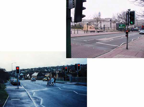
Figure 4-22. Zigzag pavement markings to warn motorists of a pedestrian crossing.
The United Kingdom has developed a number of innovative signalized pedestrian crossings that rely on the latest detector technology to improve safety and traffic operations. The PUFFIN crossing uses pedestrian detectors to automatically vary the length of the pedestrian phase, giving pedestrians the time needed to cross (Figures 4-23 and 4-24).
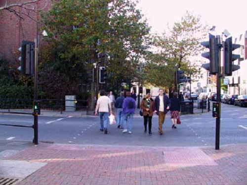
Figure 4-23. PUFFIN crossing in the United Kingdom.
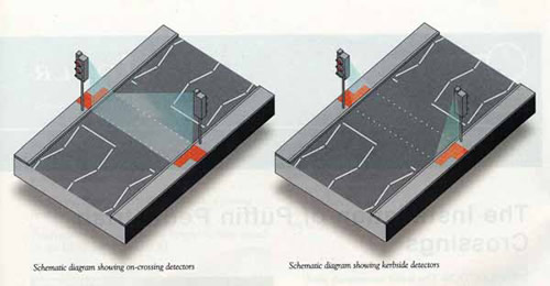
Figure 4-24. Schematic layout of a PUFFIN crossing in the United Kingdom.
Pedestrian poles placed on the near side of the road replace farside signals. On receiving a pedestrian call from a push button, the controller checks the curbside presence detector. If a pedestrian is present, the pedestrian phase is called and a light is illuminated, informing the pedestrian of the call. If the output of the curbside presence detector disappears (the pedestrian has crossed on red) the pedestrian phase call is canceled. When the pedestrian phase is started, the green walking man appears on a nearside signal. Pedestrians within the crosswalk are monitored by the crossing detectors and given sufficient time to cross the roadway. After the green man is extinguished, the red man is illuminated, signaling to pedestrians that they should not begin crossing. Maximum allowable crossing times are preset for each site. If the maximum allowable crossing times are exceeded, vehicular traffic is given a red/amber, then green signal. On divided roadways with a median, PUFFINs are often operated as two separate crossings with a staggered median that forces pedestrians to turn and face oncoming vehicular traffic (Figure 4-25).
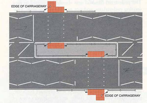
Figure 4-25. Schematic layout for a staggered PUFFIN crossing in the United Kingdom.
Some benefits of PUFFIN crossings include the following:
PUFFIN technology is also being applied to shared bicycle-pedestrian crossings (e.g., TOUCAN) and equestrian crossings.
High-volume, congested intersections are striped with yellow crosshatches (Figure 4-26). Drivers can be cited for entering the intersection and stopping in the crosshatched area because the exit lanes are blocked by stationary vehicles, although under some circumstances (crosshatched area is blocked by opposing vehicles turning right) drivers are allowed to enter the area.
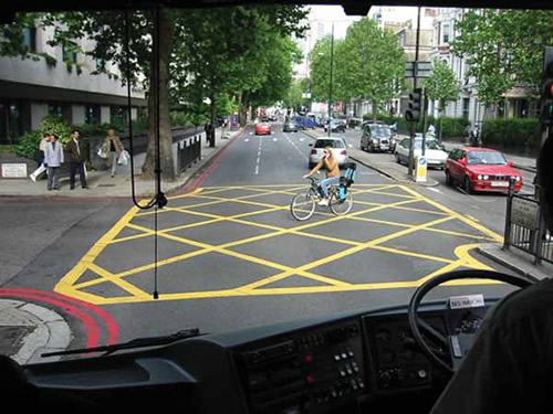
Figure 4-26. Yellow crosshatched intersection in the United Kingdom.
Signs are posted before locations where turns are restricted to tell drivers how to use other routes to reach their intended destination (Figure 4-27).
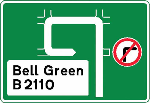
Figure 4-27. Restricted-turn sign.

