U.S. Department of Transportation
Federal Highway Administration
1200 New Jersey Avenue, SE
Washington, DC 20590
202-366-4000
As mentioned earlier, tunnel lighting has been upgraded in the past 10 years. As defined in the technical report, Guide for the Lighting of Road Tunnels and Underpasses, CIE 88, 1990, good tunnel lighting should "ensure that traffic, both during day and nighttime, can approach, pass through, and leave a tunnel, at the designated speed, with a degree of safety and comfort not less than that along adjacent stretches of open road."
In the past 10 years, techniques for excavating tunnels have improved, making tunnels a more attractive option. For example, Finland is currently working on a bypass that goes under, not around, the City of Helsinki. Additionally, while typical tunnels are straight drive-throughs, the team observed tunnels in Europe that contained merges and diverges and the team even visited an underground roundabout (figure 24). The underground roundabout, which is part of a mass transit station at Frauenfeld, in the Thurgau Canton, Switzerland, includes not only through roadways, but also an entrance and exit to an underground parking lot (figure 25).
Figure 24. Underground roundabout, Switzerland.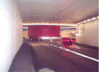
Figure 25. Underground roundabout entrance and exit feeds to underground parking.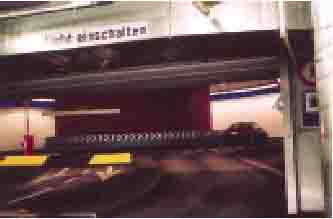
Swiss experts believe that good wall luminance is necessary to provide good guidance for motorists. Additionally, they have observed that most people perceive tunnels lit with fluorescent sources to be brighter and more comfortable than tunnels lit on the road to the same level with point sources, probably because of the higher wall luminance normally attained with fluorescent luminaires. Although various light sources are being used, long tunnels are generally lit with electronically ballasted, dimmable fluorescents. That approach easily adapts to the integrated control systems used on all the tunnels that the team observed. The integrated systems use a luminance meter to adjust the light level in the threshold zone. Lighting control systems can be integrated into the traffic management systems, and traffic volume can be added to the control elements. (Traffic control centers are discussed later under Future Developments.)
The primary difficulty in tunnel lighting is determining the correct lighting level to be installed in the threshold. In theory, "just enough light" is necessary to meet the requirement cited in CIE 88. Less than "just enough light" causes the traffic to slow down or frequent crashes to occur. Higher lighting than necessary wastes money, both on installed and maintenance costs. Determinations become more complex with the realization that the lighting decision typically has to be made before the tunnel is built. For all of these reasons, the panel was shown more tunnel lighting than any other type of lighting. The team members were greatly impressed with what they saw (figures 26 to 30).
Figure 26. Tunnel in Lyon, France.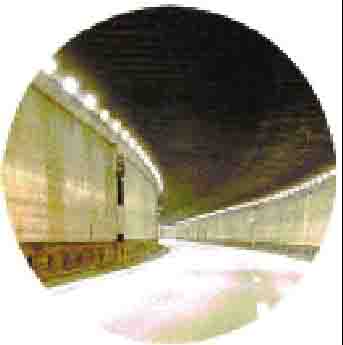
Figure 27. Tunnel in Helsinki, Finland.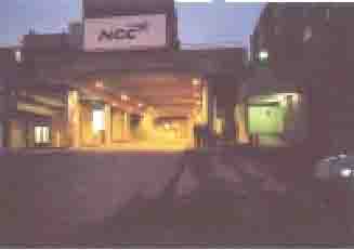
Figure 28. Tunnel at Schipol Airport, the Netherlands. The sunscreens are not actually needed, because of the counter-beam threshold lighting. They were left in place for aesthetic reasons.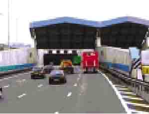
Figure 29. Milchbuck Tunnel, Switzerland.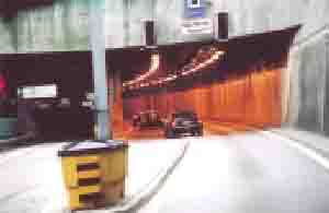
Figure 30. Wevelgem Tunnel, Belgium.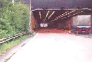
In the pilot installation of the Wevelgem Tunnel, the threshold luminance of the counter-beam system (Lth, CBL: 400 cd/m2) was purposely set equal to the threshold luminance of the symmetric system (Lth, Sym: 400 cd/m2) in order to evaluate the visibility of the targets. Figure 30 shows how the counter-beam lighting is washed out by the outside natural light. This lack of negative contrast in the beginning of the threshold results from daylight penetration (up to 70 m), reflected light from the walls and pavement, and veiling, caused by the natural brightness present in the atmospheric luminance (LATM). The Belgians found that, whatever the lighting system, there were always invisibility zones for a target with a fixed reflectance factor. These zones are of variable length and position from one system to another. Belgians do not lower the threshold luminance requirement when counter-beam lighting is used.
When using counter-beam lighting, the Swiss noted that large trucks traveling through tunnels (figure 31) absorb the light coming from the luminaries, creating a lower light level as well as shadows. Also, black trucks are hard to see. Regardless, the Swiss still believe that counter-beam offers the best solution, except in tunnels with a very high level of truck traffic.
Figure 31. Milchbuck Tunnel, Switzerland.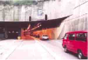
Based on experience, the Swiss believe that if sunscreens are used, they must be waterproof. A screen that is not watertight will allow water to drip on the roadway and refreeze.
In the Netherlands, counter-beam lighting, instead of sunscreens, has become more widely used because it is less expensive. Typically, the threshold luminance levels used in the Netherlands, at a design speed of 120 km/h, are 200 to 250 cd/m2, based on using counter-beam (symmetrical is higher). Dutch designers believe that the current CEN document is 1.5 to 2 times too high and that CIE recommendations are about 20 percent too low.
Recently, the Belgians told us that the Belgian designers have shown, through a European survey made in the European Working Group for Tunnel Lighting (CEN/ WG6) that, for the large majority of the tunnels, countries rigorously follow the CIE 88 (1990) recommendations for the threshold zone lighting. Their experience with these lighting levels has been reported positively.
In addition, the Dutch have developed a design method called the "Black Window." The Black Window is used for deciding whether lighting is required for short tunnels. Figure 32 is a diagram of the method, and figure 33 illustrates actual examples.
Figure 32. Black Window method, the Netherlands.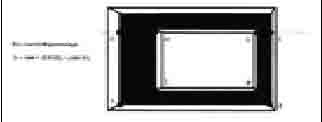
Figure 33. Examples of Black Windows.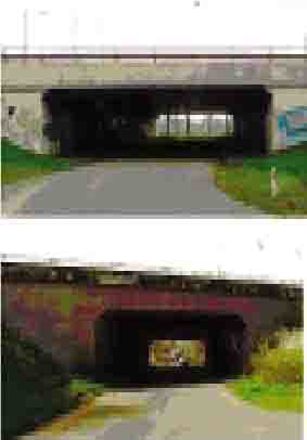
In the diagram, A, B, C, and D define the area of the entrance portal. E, F, G, and H define the exit.
For D < 20%, lighting is installed.
For D > 50%, no lighting is required.
For D > 20% or < 50%, a study is required.
The method examines what percentage of the typical automobile that passes through the tunnel is visible. If it is 30 percent visible, then no lighting is installed. If it is less than 30 percent visible, then lighting is installed. Lighting is not required on either of the examples in figure 33, because more than 30 percent of a typical automobile is visible.
Based on information from Japan, where tunnel walls are painted a dark color, the Dutch conducted an interesting experiment on the benefits of dark or light walls in tunnels. They eliminated cleaning on one of the tunnels for a period of one and a half years and had no change in crash rates.
| << Previous | Contents | Next >> |

