U.S. Department of Transportation
Federal Highway Administration
1200 New Jersey Avenue, SE
Washington, DC 20590
202-366-4000
In the area of future developments, the panel was very interested in investigating cutting-edge lighting research as well as anticipated major advancements in the art and science of roadway lighting.
All the countries that the team visited, with the exception of Switzerland, are members of the EU, and substantial effort is going into the harmonized CEN Lighting Standards. When the harmonized CEN documents are adopted, they will replace individual countries' standards, which were generally based on the CIE. This is an example of the impact of the EU now and in the future.
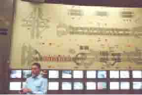
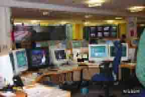
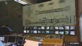
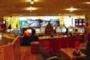
The panel visited two traffic control centers (TCC): one in Finland and one in Switzerland (figures 53 and 54).
The TCCs are used to improve traffic flow, provide traffic information, and control and manage traffic demand. The Finnish center can monitor the weather throughout the entire country and, when needed, give information directly to motorists by interrupting car radio programs. Motorists do not need to be tuned to any particular frequency. The center can also remotely change posted speed limits.
Figures 53. & 54. Views of a TCC in Switzerland (left) and Finland (right).
In the Netherlands, the origins of dynamic roadway lighting can be traced to the Energy Crisis of the 1970s. During that period, some luminaires were turned off to save energy. While there was an increase in accidents, it was not a large increase. (Some areas of the United States noted significant increases in accidents when the same approach was used). Over the following 15 years, there was movement by the Netherlands to lower the lighting levels from 2 cd/m2 (as recommended by CIE) to 1 cd/m2, retaining the recommended uniformity ratios.
Since 1995, the Netherlands has installed and operated a dynamically lighted roadway that can be adjusted to any of three lighting levels, depending on the amount of traffic, time of day, and weather conditions. The low level is 0.2 cd/m2 (figure 55), the normal level is 1 cd/m2 (figure 56), and the high level is 2.0 cd/m2 (figure 57). The different light levels are obtained through the use of electronically controlled, dimmable HPS ballasts.
Figure 55. Low level of roadway lighting, the Netherlands.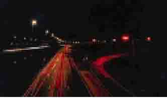
Figure 56. Normal level of roadway lighting.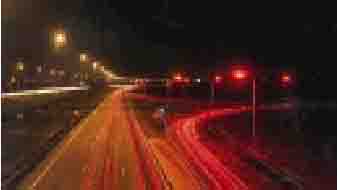
Figure 57. High level of roadway lighting.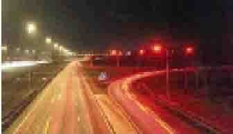
To set a baseline for the dynamic road section, Dutch experts have collected and analyzed accident data. Unfortunately, the dynamic section was too short and the statistical sample size was too small to draw conclusions between the 1-cd/m2 and 2-cd/m2 light levels. In an evaluation of an extensive set of methods (inductive loop detectors, instrumented vehicles, video observations, questionnaires), it was concluded that, under low traffic volumes (less than 800 vehicles per hour) and favorable weather conditions, the low level (0.2 cd/m2) can be applied. Accidents rates for the low-level lighting have been acceptable. To continue gathering information on dynamic road lighting, the Dutch have installed a second system, which only operates at 1 cd/m2 and 0.2 cd/m2.
In Finland, a consortium of three organizations (FORTUM, SITO, and VTT) is experimenting with a dynamic road lighting system on a 3.5-km segment of Route 1
(Oinola to Saukkola), with about 9,000 ADT, on a two-lane road. The system uses a continuous integration of traffic volume and weather conditions to determine the speed limits and roadway lighting levels. A measuring device (meter) is used to determine whether the pavement is wet, dry, or snow-covered. The control system tries to keep the luminance of the roadway constant by varying the lumen output of each luminaire. The meters also can determine which luminaires are not functioning properly. Dimmers made by Philips Telemanagement control individual luminaires. The schedule called for testing of the system to begin in autumn of 2000.
In the mid-1990s, environmental studies concluded that a lighted roadway could be a barrier to wildlife movement. In addition, a number of environmentalists suggested that darkness was a natural and good thing. A number of environmentally sensitive areas in the north of the Netherlands are referred to as "scenic areas." In the scenic areas, the current lighting approach is multifaceted and includes not installing lighting, installing lighting that can be dimmed, and an active investigation into the use of lighting as a guidance system.
Experts in the Netherlands are researching the acceptability of a number of different types of guidance systems. Under investigation are light-emitting diode (LED) pavement markers, LED post delineators, LED pavement-marker stripes, fiber-optic "side sights" (fiber optics attached to a guardrail, with light emanating along the entire length), and fiber optic "end lights" (in-pavement fiber optics with ends extending up and out of the pavement surface at fixed intervals with light emanating from the tips of the cables). These systems are used where additional guidance is needed and are typically operated between 11:30 PM and 6 AM. Figure 58 illustrates the types of systems.
To date, findings of the Dutch investigations indicate the following:
Figure 58. Dutch guidance systems under investigation.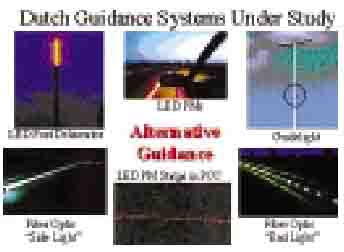
The panel observed in-road, fiber-optic delineators in Switzerland, as well, which are shown in figures 59a and b.
In addition to the research by the Dutch, the French have a study under way comparing lighting, retroreflectivity, and active luminous devices. Also, Helsinki University is working in the area of mesopic vision (luminance levels that are typically used in roadway lighting) and use of LEDs in lighting. There is an extensive amount of research being conducted in this area.
Figures 59a & 59b. In-road, fiber-optic delineators.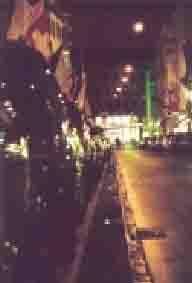
Some of the newer surfaces that are not included in the development of the original R-tables include quiet and water-draining pavements, as well as very thin, asphaltic concretes and surface dressings. Additionally, there is an increase in the use of bright and colored road surfaces, as shown in figure 60.
Figure 60. Examples of colored pavement.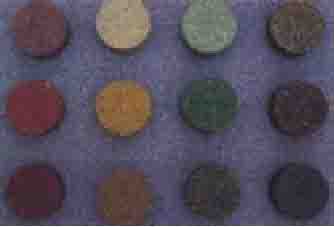
Because of the evolution of road surface technology, the French are conducting research in the area of photometric properties of road surfaces. Figures 61 and 62 show applications of colored pavements.
Figure 61. & 62 Application of colored pavement.
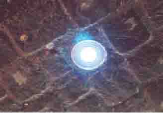
There is a need for new pavement reflectance measuring equipment as well as data for observation angles, other than 1 degree downward. Figure 63 illustrates a typical view that a motorist sees inside a tunnel. Here, the driver will usually shorten his gaze to closer objects both on and off the roadway, depending on his rate of speed. Data are needed for the closer observation angles.
Figure 63. Typical motorist's view of tunnel.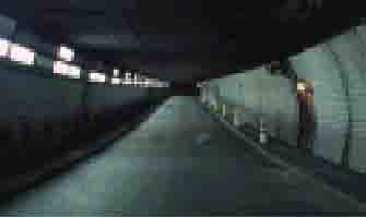
In Belgium, R-Tech is building a reflectometer to measure pavement reflectance at varying alpha, beta, and gamma angles. In France, with use of a ray tracing technique, the French are developing a virtual reflectometer (figure 64) to predict current and future pavement reflectance for all angles.
Figure 64. Virtual reflectometer, France.
Worldwide, the volume of vehicular traffic is increasing. To keep traffic moving through tunnels in the daytime, the lighting community has increased the amount of light installed so that the "black hole" that used to be present at the tunnel portal has been improved to a "gray hole." The intent is to make sure drivers can see well enough into the tunnel so they don't slow down when entering the tunnel. While this has been accomplished, it has been expensive to install and operate - offsetting sunlight is not cheap! As a result, those responsible for lighting tunnels are always looking for ways to accomplish the necessary visual task for less money.
In Switzerland, an example of partial tunnel lighting for a 120-m-long tunnel was cited. The partial-lighting approach for short tunnels may provide the needed visibility while saving energy. It utilizes a known phenomenon: natural daytime lighting typically penetrates the portals of the tunnel about 40 m. Taking advantage of that, artificial lighting is only installed in the middle 40 m of the tunnel. Installing only one-third as much lighting saves a great deal of energy, which makes it very appealing.
Johan Alferdinck of the research firm TNO Human Factors, the Netherlands, presented a paper examining the effects of light sources on color contrast in tunnel lighting. The purpose of the research is to answer the question, "Based on luminance contrast, does the color of the light source add anything to this, so that I can reduce the light level in the threshold?" While further research needs to be conducted, part of the conclusion reached is that the use of colored light sources in tunnel lighting is superior in all conditions. Figure 65 shows colored targets with two different types of lighting. Note the difficulty in target detection when veiling luminance is added.
Figure 65. Effects of tunnel lighting color.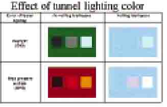
Control of light levels in tunnels has traditionally been done using a technique that looks at a 20-degree cone and is referred to as "L20." Another technique, called Lseq., which uses a cone of view that is more heavily weighted in the center, also can be used to control the lighting. Jean-Marie Dijon, along with R-Tech, in Belgium, believe that both the L20 and Lseq. controls should be placed on the same tunnel and comparisons made to determine which method performed the best.
Dr. Peter Blaser, in Switzerland, stated that there is a need for research on the visual task in tunnels. He suggested that, for today's traffic conditions, small targets in an empty tunnel do not adequately describe the situation.
The active research items discussed above are only a portion of the large number of projects under way. As was clear from visiting five countries, the Europeans take the task of advancing the art and science of lighting seriously. While some of the research is funded by private industry, much of it is paid for by various government agencies. For example, the Finnish Road Administration spends 1.5 percent of its annual budget on research and development.
| << Previous | Contents | Next >> |

